1 Introduction
Refer to Bulletin 02-008 for Service Field Test Unit (Part No. 13927) recommendations. Refer to Figure
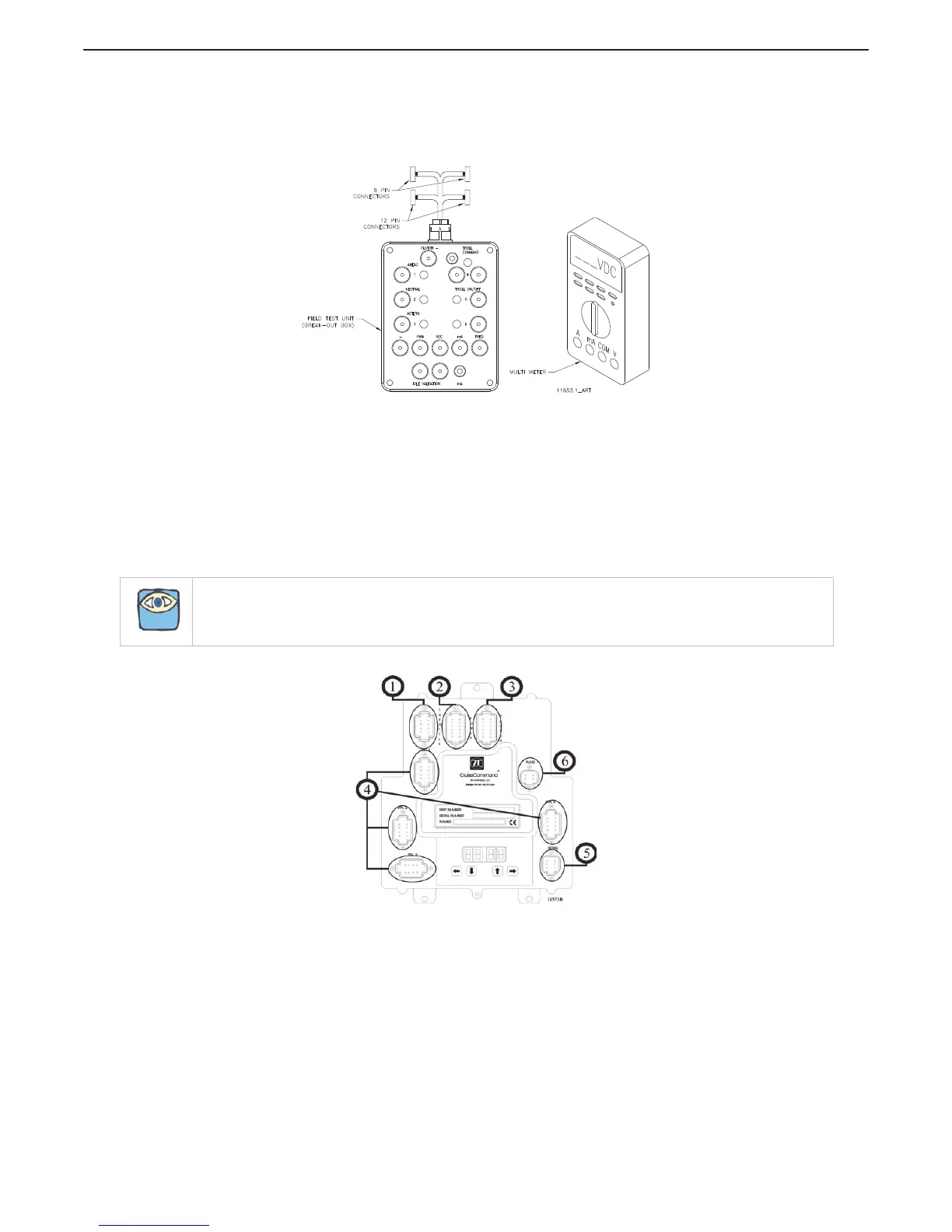
MM13927-1: .Service Field Test Unit (Break-out Box) for an example of the Test Unit and a Multimeter
Figure MM13927-1: .Service Field Test Unit (Break-out Box)
The Service Field Test Unit, hereafter referred to as the “Break-out Box”, is recommended for use with all
CruiseCommand Processors (Part No. 785CE) and with ClearCommand Processors (Part No. 9XXX Series)
that have pluggable (Pigtail) Throttle, Clutch or Troll Connections.
The procedures for testing the various outputs of the ClearCommand and CruiseCommand Processors are
similar, with the exception of where they connect to the respective Processor. Figure MM13927-2:
CruiseCommand Connector Locations indicates the location of the connectors on the CruiseCommand
Processor and Figure MM13927-3: Example of CLEARCommand Pigtail Locations the typical pigtail plugs
on a 9000 Series ClearCommand Processor.
Figure MM13927-2: CruiseCommand Connector Locations
NOTE: Not all ClearCommand Processors have all of the pigtails shown in Figure MM13927-3: Example of
CLEARCommand Pigtail Locations. Only the pigtails that are required for a specific application are installed in
a ClearCommand Processor.

 Loading...