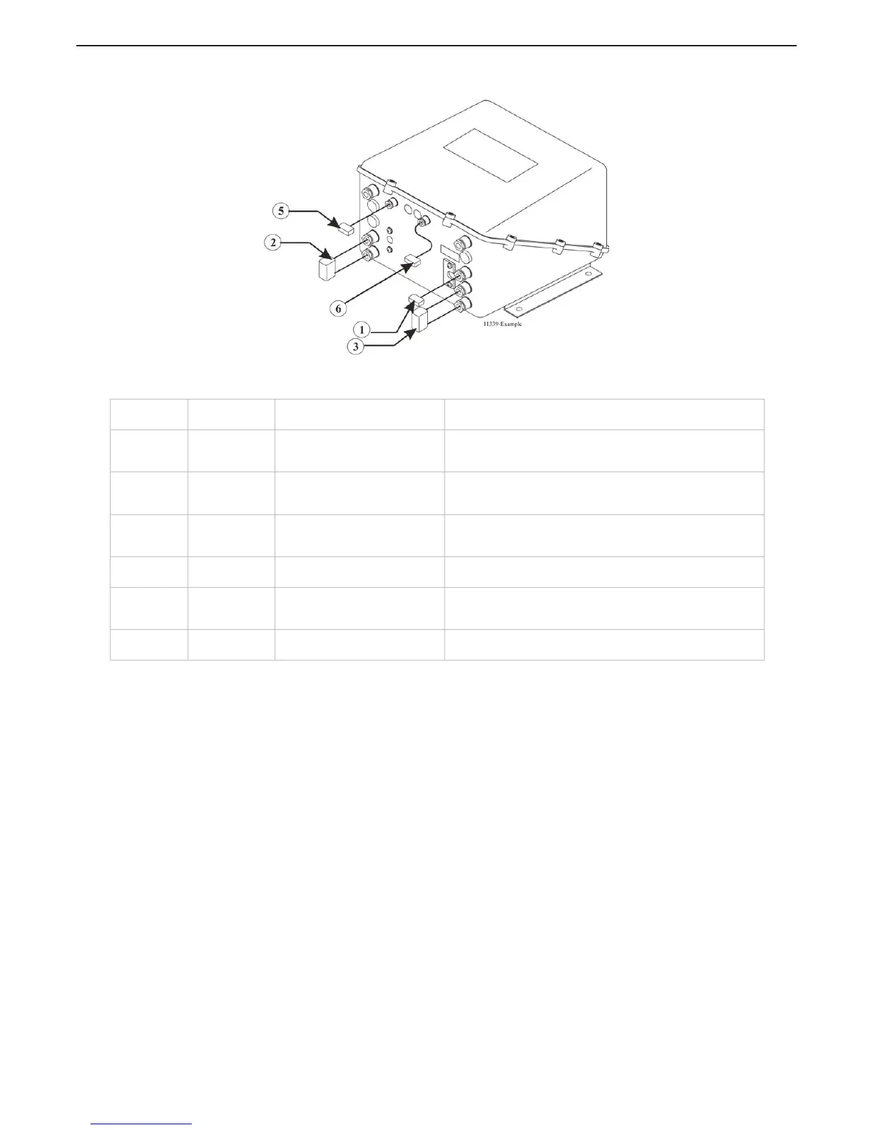
Figure MM13927-3: Example of CLEARCommand Pigtail Locations
The actual procedures for using the Break-out Box are the same for CruiseCommand and ClearCommand
Processors. However, the adjustment within the Processor to obtain the correct output may differ. The
appropriate Installation Manual must be referred to when making the adjustments.
Designation
#
Description Harness Type Harness Use
1 Black 8 Pin Throttle Connector/Pigtail
The throttle signal is output from this connector/pigtail. The
signal may be in the form of Pulse Width Modulation (PWM),
Voltage, Current, or Frequency.
2 Black 12 Pin Power Connector/Pigtail
This connector/pigtail contains the inputs and outputs for
Main Processor Power, Start Interlock, Clutch Oil Pressure
Interlock, and External Alarm Circuit.
3 Gray 12 Pin Clutch Connector/Pigtail
The external connections for Clutch Power, Ahead, Astern,
and Neutral Solenoids, Troll On/ Off, and Proportional
Solenoids are made at this connector/pigtail.
4 Gray 8 Pin Control Head Connector
All the required connections for the Remote Control Stations
are made at these connectors.
5 Gray 6 Pin
Serial Communication
Connector/Pigtail
The Serial Communication connections between multiple
Processors in applications with more than one Processor at
this connector/pigtail.
6 Gray 4 Pin
Tachometer Sensor Connector/
Pigtail
The input signal from a Tachometer or Shaft Speed Sensor
connects to this connector/pigtail.

 Loading...