4.4.4 9000 Series Circuit Board Termination Points
On the 9000 Series Processors, in lieu of using Harnesses for engine, clutch, or troll connections the
Processors can be ordered with no pigtails installed or the pigtails be removed. The above
connections must then be hard-wired directly to the circuit board.
Refer to Table 4-1: ClearCommand Processor Optional Hard-Wiring Cable List for the Processor being
used in this application.
Locations 1 - 9 circuit board termination points are the same for all Processors and are shown on
Figure 4-5: Standard Enclosure Cable Holes.
Refer to Figure 4-6: Standard Circuit Board Hard-Wired Termination Points for specific termination
points for the engine, clutch or troll connections required for the Processor being used in this
application.
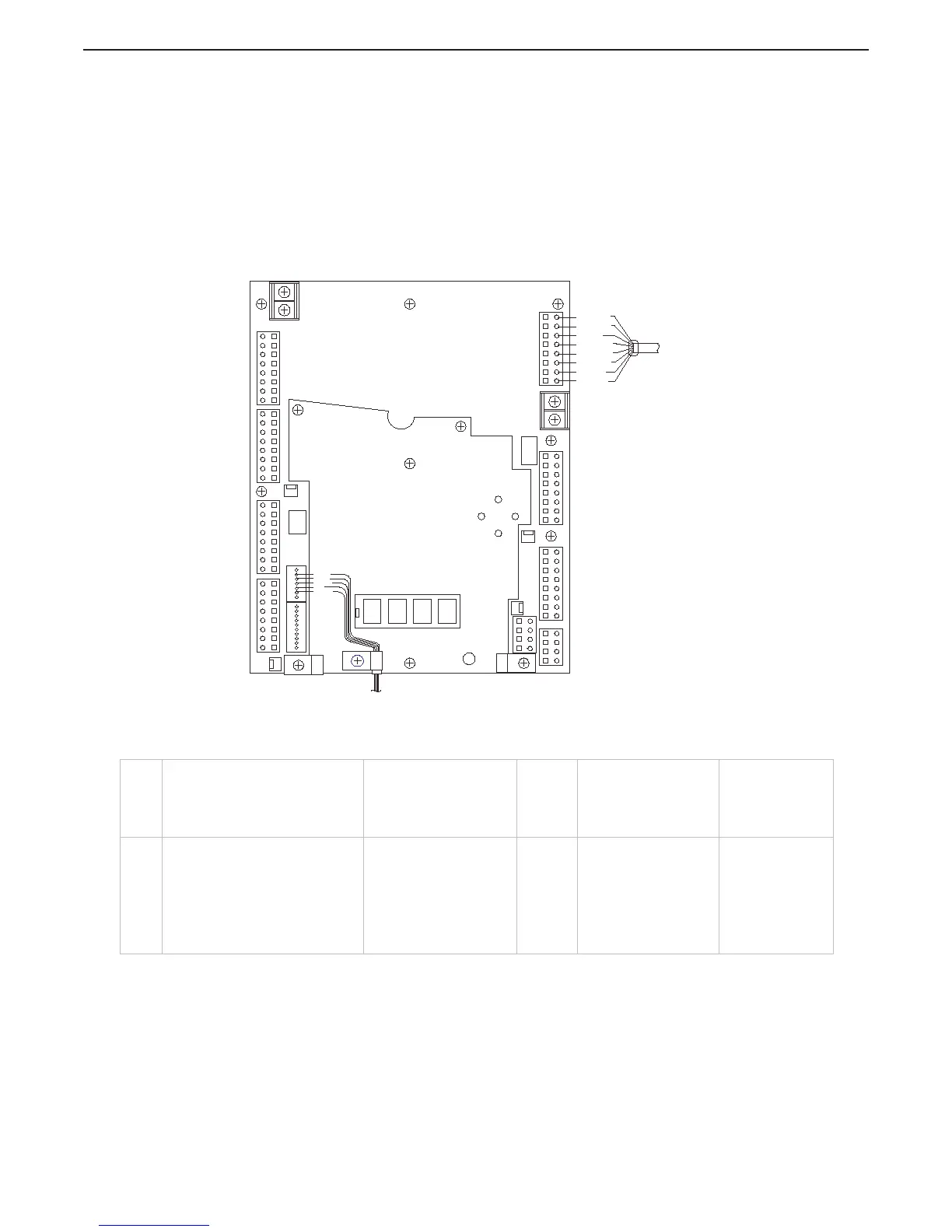
Figure 4-11: 9000 Series Circuit Board Hard-Wired Termination Points
12. Throttle: TB8
Brown - 3,
Red - 4,
Orange - 5,
White - 6,
Black - 7
10 Clutch: TB11
Black - 1
Brown - 2
Yellow - 5
Green - 6
10 & 11. Clutch/Troll: TB11
Black - 1
Brown - 2
Red - 3
Orange - 4
Yellow - 5
Green - 6
Blue - 7
White - 8
LEFT
RIGHT
UP
+
-
SERIAL
STATION 2
OPI ALARM
TACH
STATION 5
SOLENOIDS
DIGITAL INPUTS
START
INTERLOCK
ELEC-THR
STATION 3
CLUTCH
STATION 1
STATION 4
AUTO-
TROLL
THROTTLE
POWER
JMP1
P3
DS4
DS2
DS3
DS1
P4
J3
P1
TB9
TB7
TB8
TB4
TB5
TB3
PB1
TB11
TB6
PB2
TB10
TB2
TB1
1 2 3
4
2 3 5 6 8
4
7 9 10
1
1
3 4 6 7
2
5
7 6 4 3
1
8 5 2
7 6
4 3
8
5 2
1
7 6
4 3
8
5 2
1
7 6
4 3
1
8
5 2
1 2
3 2
4
1
7 6 4 3 1
8 5 2
7 6
4 3 1
8 5
2
J1
DOWN
P2
BROWN
ORANGE
WHITE
BLACK
RED
7 6 4 3 1
8 5
2
CLUTCH SOLENOIDS OR
CLUTCH/TROLL SOLENOIDS
ELECTRONIC THROTTLE
12284.2_ART
11.
10.
RED
ORANGE
BLUE
BLACK
BROWN
GREEN
WHITE
YELLOW

 Loading...