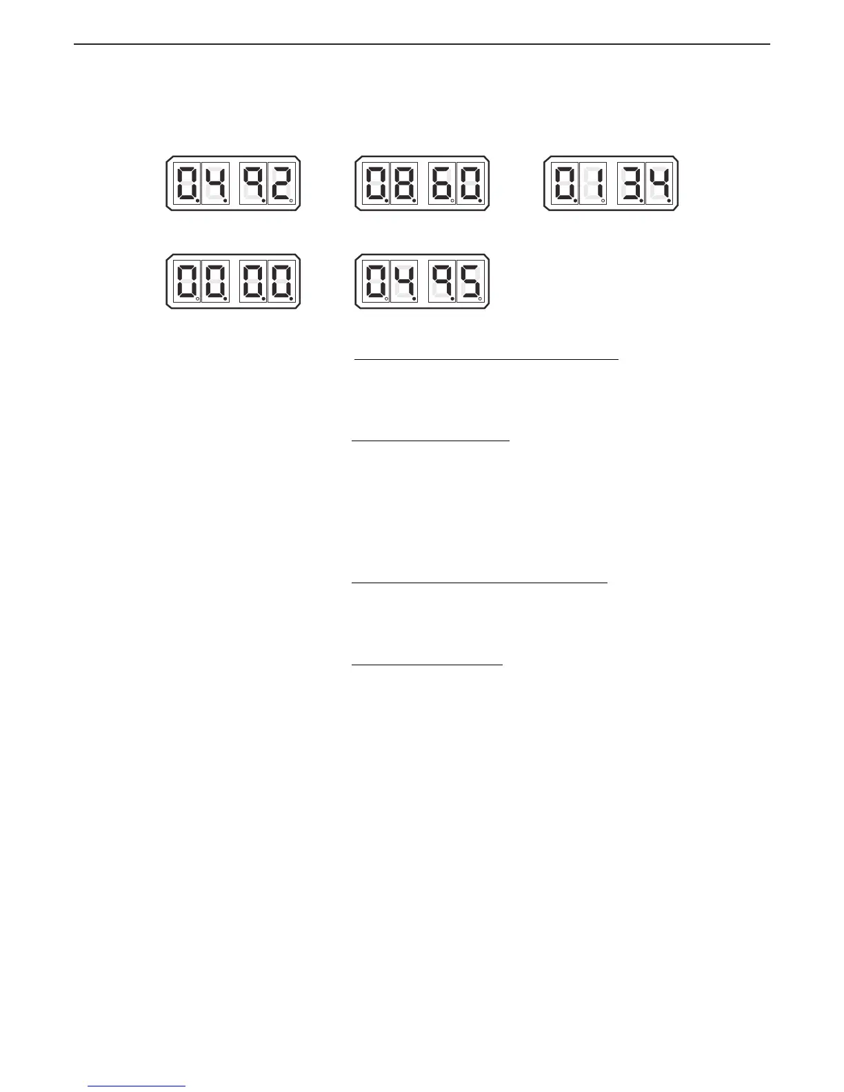
appropriate A/D (Analog/Digital) value for the present position of the Control Head’s lever
will be shown, as in the examples below:
E An A/D value of 910 or greater will generate an Error Code. The code will be 13 to 22
(Control Head # Faulted High), depending on which Station has the high Command Signal.
• If the A/D value is greater than 910, but less than 990
, one of the following
may be the cause:
1. The Control Head’s potentiometer is out of calibration.
2. The potentiometer is defective.
In either case, it is recommended that the Control Head is
replaced.
• If the A/D value is 995 or higher
, most likely the potentiometer’s ground has
been lost.
• Right hand Control Heads have a jumper between pins 3 and 5 if a Harness is
used. This jumper provides the potentiometers ground.
• Left hand Control heads have a jumper between pins 3 and 7 is a Harness is
used. This jumper provides the potentiometers ground.
• The potentiometer ground connection for Control Heads which are hard-wired
to the Processor is through the yellow wire (pin 5 on right hand and pin 7 on
left hand).
F If the A/D value is 100 or less, one of Error Codes 23- 32 (Control Head # Faulted Low) will
be shown.
• If the A/D value is less than 100, but greater than 75
, the following may be the
cause:
1. The Control Head’s potentiometer is out of calibration.
2. The potentiometer is defective.
3. A high resistance connection exists on pin 6 (green wire)
between the Control Head and Processor.
• If the A/D value is less than 75
:
1. There is an open wire between pin 6 (green wire) of the Control
Head and the Processor.
2. There is an open wire between pin 7 (blue wire) of a right hand
Control Head and the Processor.
3. There is an open wire between pin 5 (blue wire) of a left hand
Control Head and pin 7 (blue wire) of the Processor.
Figure 10-15: Display Examples of Remote Stations A/D Value
STATION 1
(N
EUTRAL COMMANDED)
S
TATION 4
(NO CONTROL HEAD CONNECTED)
S
TATION 2
(F
ULL AHEAD COMMANDED)
S
TATION 5
(NEUTRAL COMMANDED)
S
TATION 3
(F
ULL ASTERN COMMANDED)

 Loading...