The available Values are:
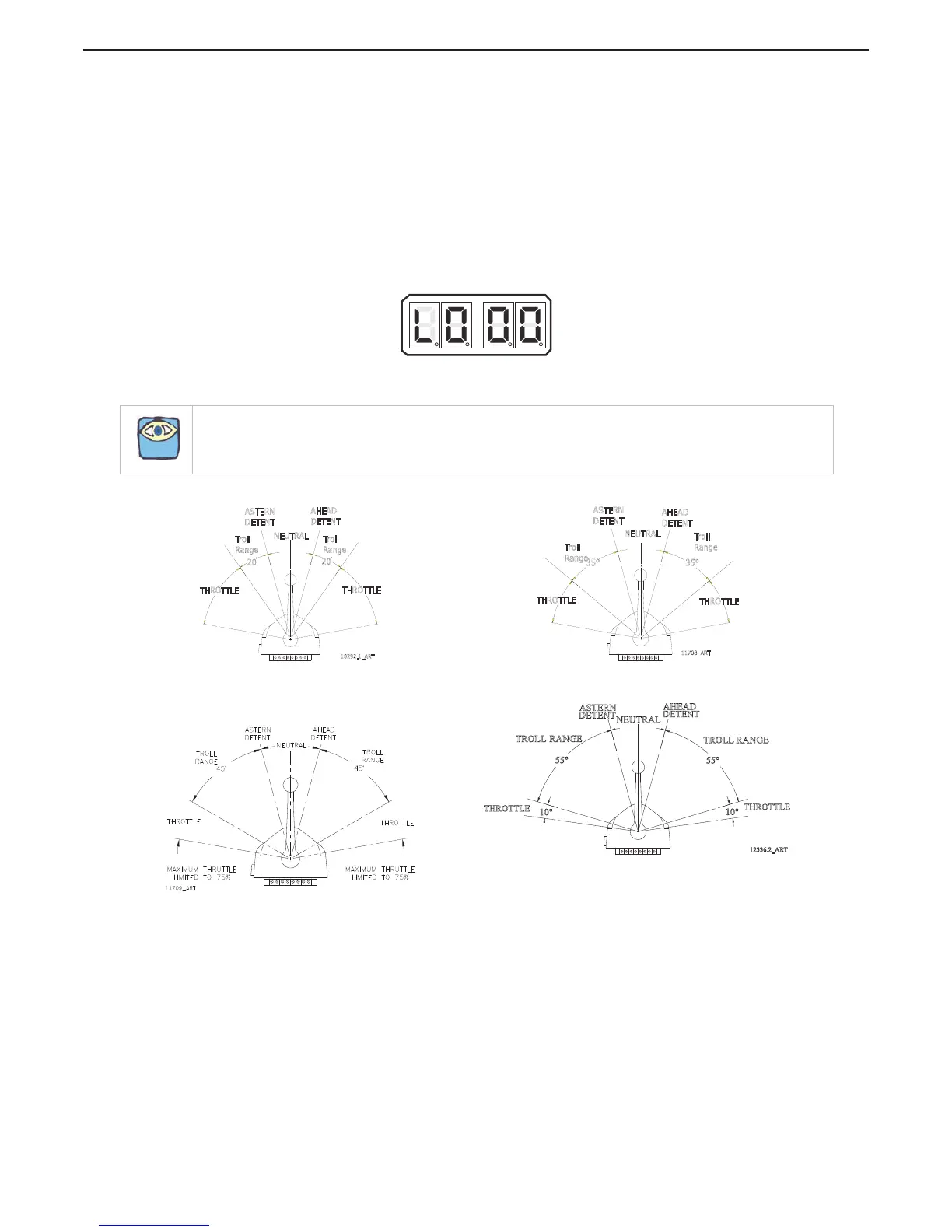
00 No Troll (Default Value)
01 20 Degrees – Type 1
02 35 Degrees – Type 2
03 45 Degrees – Type 3 (Throttle limited to 75%).
04 55 Degrees - Type 4 (Throttle limited to 10%).
To change the Value (Refer to Sections Section 5.2: Activating Set Up Mode and Section
5.3: Storing Values To Memory):
A Scroll to Function Code L0.
B Activate Set Up Mode.
C Scroll Up or Down to the desired Value.
D Store the Value to memory
Figure 5-44: Display LED Function L0 Set Up Activated.
NOTE: Function Codes L1 thru L6 are not displayed on the Processor Display LED unless Function Code L0 is
set to a Value other than 00.
Figure 5-45: Control Head 20 Degree Troll Range - Type 1 Figure 5-46: Control Head 35 Degree Troll Range - Type 2
Figure 5-47: Control Head 45 Degree Troll Range - Type 3
Figure 5-48: Control Head 55 Degree Troll Range - Type 4
AHEAD
DETENT
Troll
Range
ASTERN
DETENT
Troll
Range
10292.1_ART
THROTTLE
20
NEUTRAL
20
THROTTLE
AHEAD
DETENT
Troll
Range
ASTERN
DETENT
Troll
Range
THROTTLE
NEUTRAL
THROTTLE
11708_ART
35°
35°
DETENT
AHEAD
DETENT
ASTERN
12336.2_ART
RANGE
TROLL
RANGE
TROLL
55°
NEUTRAL
55°
10°
10°
THROTTLE
THROTTLE

 Loading...