C Insert the Break-out Box between the number 1 Processor connector/pigtail and the Throttle
Harness as shown in Figure MM13927-7: Throttle connection (PWM with Duty Cycle Meter).
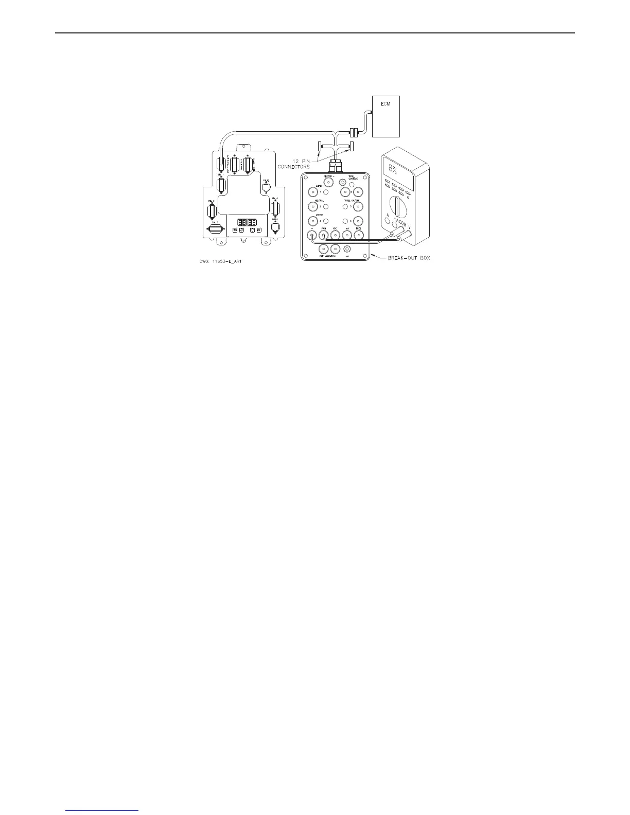
Figure MM13927-7: Throttle connection (PWM with Duty Cycle Meter)
D Set up the Multimeter to measure Duty Cycle and plug the black lead into the Break-out Box
black socket labeled “-” and the red lead into the socket labeled “PWM”.
E Turn power ‘On’ to the Caterpillar ECM (Electronic Control Module) and to the Processor.
F The measurement should be approximately 8% duty Cycle.
G Move the Control Head lever to the Full Throttle position while depressing the Transfer
Button (Throttle Only Mode).
H The measurement will increase from 8% to 91- 93%.
2.1.5 Frequency (Hz.)
A Ensure power is removed from both the Engine Electronics and the Processor.
B Disconnect the Throttle Harness from the number 1 Processor connector/pigtail.
C Insert the Break-out Box between the number 1 Processor connector/pigtail and the Throttle
Harness as shown in Figure MM13927-8: Throttle Connection (Frequency Hz).

 Loading...