Example 2
Reference Voltage4.80 VDC1023 A/D Counts
Command Voltage2.35 VDC501 A/D Counts
As you can see by the examples, even though the Command Voltages are different between
Examples 1 and 2, the resulting A/D counts, are the same because of the different Reference
Voltages. This would result in the Processor commanding the identical outputs (Clutch & Throttle) in
both cases.
A The A/D count for a specific Control Head’s lever can be seen on the Processor’s Display by
following the steps outlined in Section 10.4: Troubleshooting Diagnostic Menu.
B Once the appropriate remote station is reached, ensure that the displayed A/D Count
represents the Neutral/Idle position (485- 505 A/D counts). Command will not
be accepted
unless the Control Head’s lever is at the Neutral/Idle position.
The following table shows the appropriate A/D Counts for various Control Head lever positions:
10.6.3 Remote Station Select
The second required item for taking command is “Station Select” or depressing of the Transfer Button.
• The Transfer Button can be tested by entering the Diagnostic Menu H0.
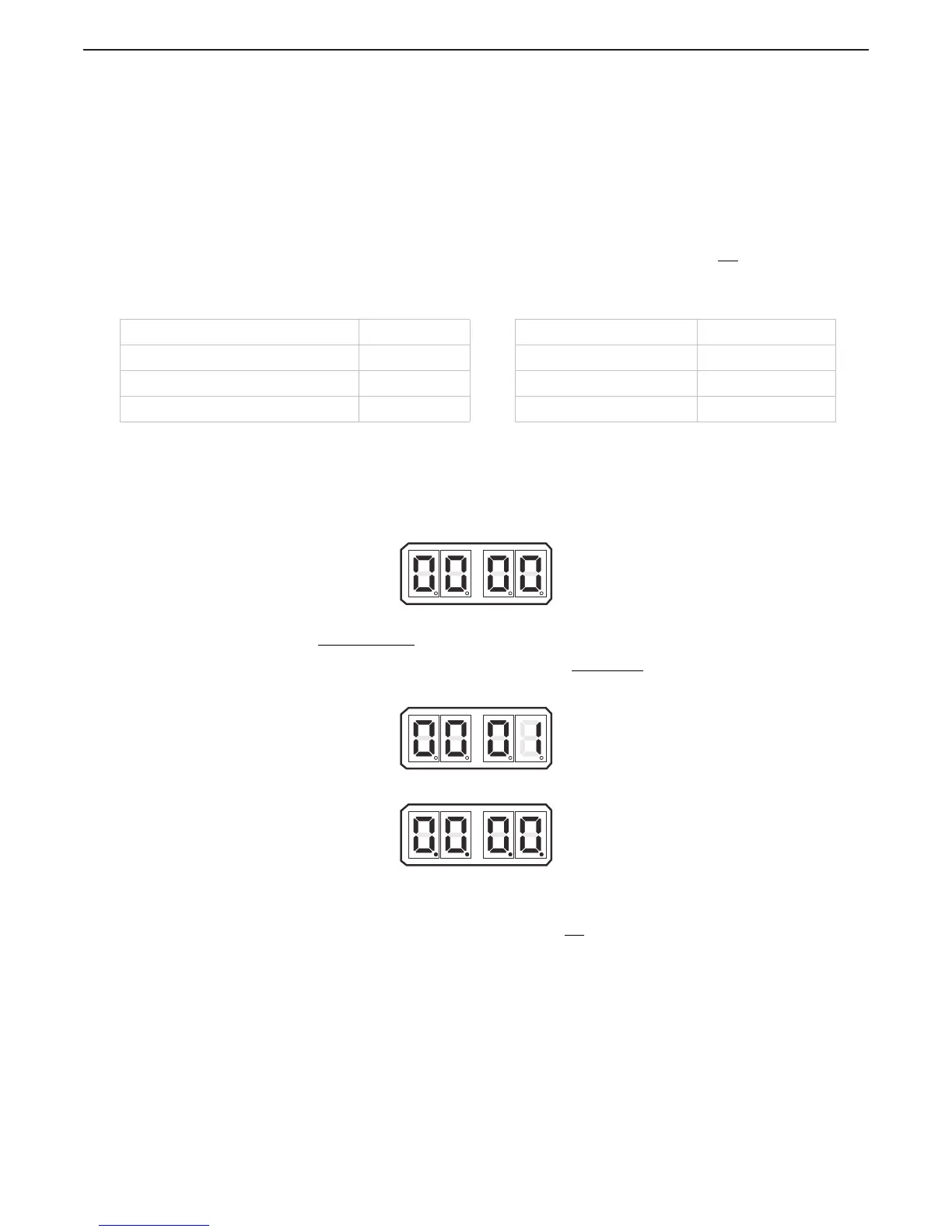
A Depress the Up or Down (scroll) Push Button until four zeroes are displayed without decimal
points as shown in Figure 10-16: Display Station A/D’s No Station Transfer Button
Depressed.
Figure 10-16: Display Station A/D’s No Station Transfer Button Depressed
B For Stations 1 - 4
when the Transfer Button is depressed, the 0 which represents that
remote station, will change to a 1 as shown in Figure 10-17: Example Display Station A/D’s
Transfer Button Depressed for Stations 1 - 4. For Station 5
when the Transfer Button is
depressed, all four decimal points will light as shown in Figure 10-18: Display Station A/D/s
Transfer Button Depressed for Station 5
Figure 10-17: Example Display Station A/D’s Transfer Button Depressed for Stations 1 - 4
Figure 10-18: Display Station A/D/s Transfer Button Depressed for Station 5
• Whenever command cannot be gained at a particular remote station, the Station Select and
Command Signals are the first to be investigated. If either the Command Signal is out of range
or the Station Select is inoperable, command will not
be accepted at that remote station.
Table 10-3: Control Head Lever A/D Counts
Control Head Lever Position A/D Count Control Head Lever Position A/D Count
Lever Out of Range Low 100 Full Astern 153 - 173
Neutral/ Idle 485 - 505 Ahead Shift Point 537
Full Ahead 821 - 841 Lever Out of Range High 910

 Loading...