4.4.5.3 Power Cable (Location 5)
A Run the length of two-conductor power cable between the DC Power Source and the
Processor.
B Make the connections at the vessel’s DC Power Source, but do not
turn power ON.
C Install a liquid tight connector into the DC POWER entry hole (No. 5). (Refer to Figure 4-5:
Standard Enclosure Cable Holes for entry hole location and Figure 4-4: Liquid Tight
Installation for cable grip installation.)
D Run enough of the two-conductor power cable through the liquid tight cable grip so that it
can be routed as shown in Figure 4-5: Standard Enclosure Cable Holes.
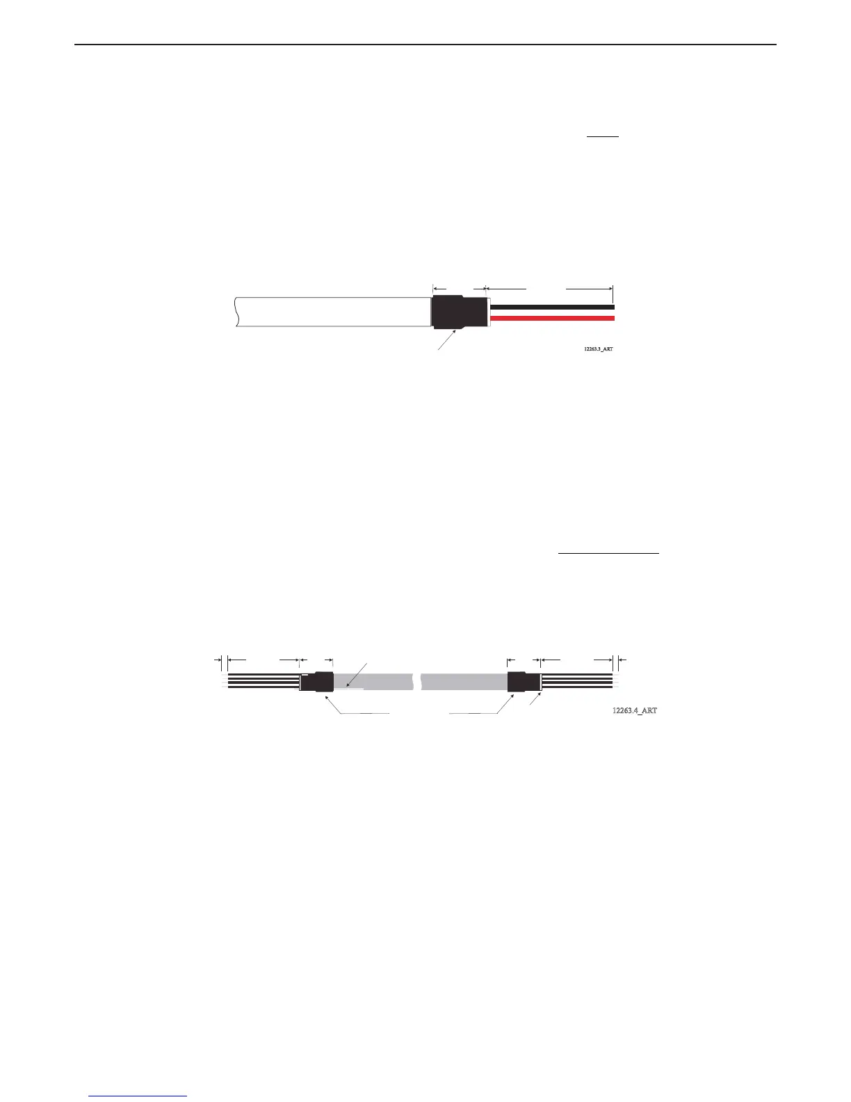
E Strip back 3 inches (76,2mm) of the PVC jacketing. Refer to Figure 4-16: Two-Conductor
Power Cable
F Strip each wire 3/8-inch (9,5mm).
G Place a 3/8 inch (9,5mm) section of shrink tubing over the cable and heat
Figure 4-16: Two-Conductor Power Cable
H Crimp fork or ring terminals to the wires.
I Connect the two-conductor cable to PB1, red lead to the terminal labeled (+) and black lead
to the terminal labeled (-), as indicated on Figure 4-10: 9221 Enclosure Cable Holes.
J Tie wrap the power cable to the Processor’s frame.
4.4.5.4 Serial Communication Cable (Location 8)
A Install 1/2 inch (12,7mm) liquid tight cable grips into hole (No.8) of the Port and Starboard
Processors. (Refer to Figure 4-5: Standard Enclosure Cable Holes for entry hole location and
Figure 4-4: Liquid Tight Installation for cable grip installation.)
B Run a four-conductor, shielded cable from the Port to the Starboard Processors.
C Strip back 3 inches (76,2mm) of PVC jacketing from both ends of the cable.
D Strip each wire 3/8 inch (9,5mm).
E Clip the drain wire flush with the PVC jacketing on the Starboard Processor
only.
F Place a 1 inch (25,4mm) section of shrink tubing over each end of the cable
G On the Port end of the cable, bend the drain wire back and tuck it under the shrink tubing so
that the drain wire end is exposed past the shrink tubing. (Refer to Figure 4-18: AC Type
Tachometer Cable)
Figure 4-17: Four-Conductor Serial Communication Cable
H Shrink the Tubing with a heat gun.
I Insert the four-conductor cable through the liquid tight connectors and tighten the nuts
J Secure the cables internally using a Clamp as shown in Figure 4-13: Clamp Views. Make
certain that the drain wire makes contact with the Clamp’s metallic surface.
K Clip the exposed drain wires flush with the Clamps.
3/8 inch
(9,5mm)
3 inches
(76,2mm)
Heat Shrink
12263.3_ART
Heat Shrink
12263.4_ART
1 inch
(25,4mm)
3 inches
(76,2mm)
3/8 inch
(9,53mm)
Drain Wire
Clip Drain Wire
1 inch
(25,4mm)
3 inches
(76,2mm)
3/8 inch
(9,53mm)
PORT PROCESSOR STARBOARD PROCESSOR

 Loading...