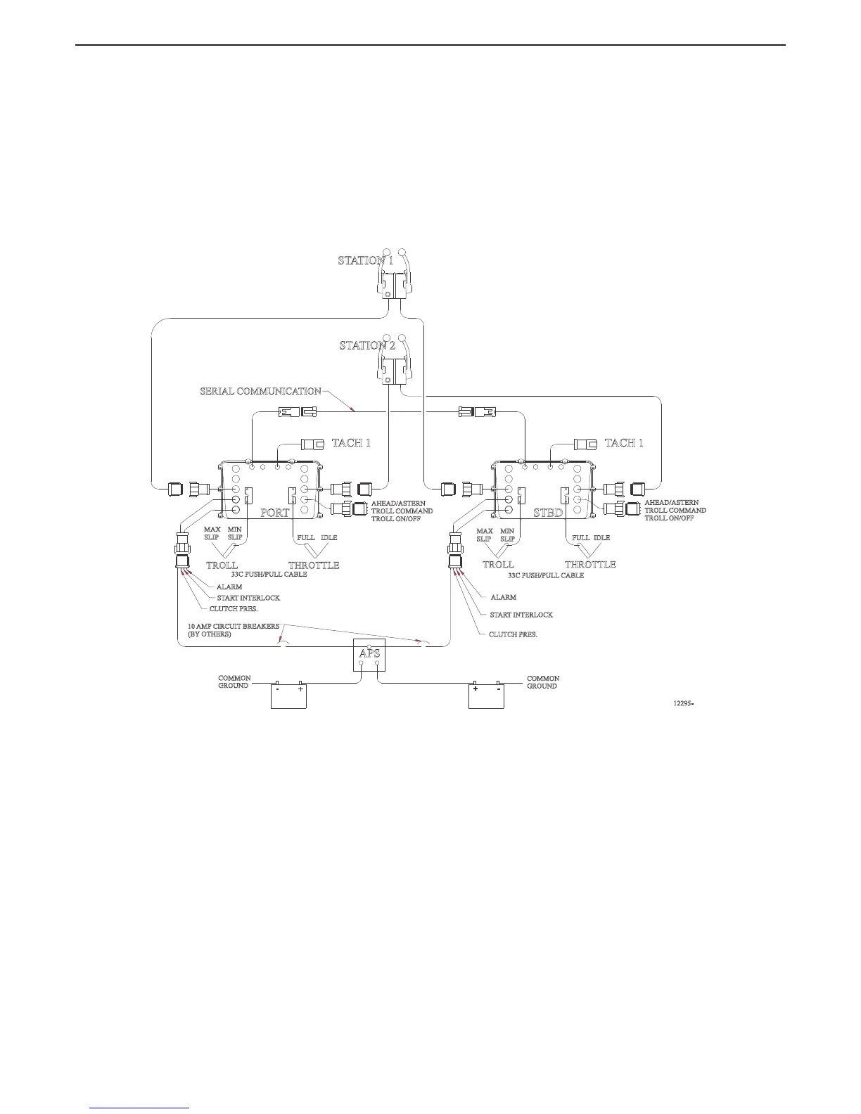
1.1.2 9121 Processor (Throttle-Servo 2, Shift-Solenoid, Troll-Servo 1)
The 9121 System is designed for pleasure and light commercial marine vessels that require remote
control of:
• mechanically actuated engines
• solenoid activated clutches
• mechanical trolling valves.
The Processor is typically mounted in the engine room area and is connected mechanically to the
vessel’s main engine throttle selector lever and trolling valve with standard 33C type push-pull cables.
The transmission is controlled via electrical cables connected to the Ahead and Astern Shift
Solenoids.
Figure 1-2: Basic 9121 ClearCommand System Diagram
IDLEFULL
33C PUSH/PULL CABLE
33C PUSH/PULL CABLE
IDLE
FULL
THROTTLETROLL
STBD
STATION 2
STATION 1
PORT
12295-
SERIAL COMMUNICATION
10 AMP CIRCUIT BREAKERS
(BY OTHERS)
COMMON
GROUND
COMMON
GROUND
+
-
+
-
APS
CLUTCH PRES.
START INTERLOCK
ALARM
START INTERLOCK
CLUTCH PRES.
ALARM
TACH 1 TACH 1
MAX
SLIP
MIN
SLIP
AHEAD/ASTERN
TROLL COMMAND
TROLL ON/OFF
AHEAD/ASTERN
TROLL COMMAND
TROLL ON/OFF
MAX
SLIP
MIN
SLIP
THROTTLETROLL

 Loading...