• When connecting the plugs, ensure that the locking mechanisms are depressed and held until
the plug is fully connected or disconnected. Refer to Figure 4-1: Harness Plug Keying
4.3.2 Standard Power/Start Interlock Harness
The Power Harness has a minimum of two cables (DC Power and Start Interlock) and may have two
more optional cables (Clutch Pressure Interlock and External Alarm Circuit).
4.3.2.1 DC Power Cable
(Refer to S-214 Automatic Power Selector Model: 13505)
A Insert the black, twelve pin plug into the Processor’s Power/Start Interlock Pigtail’s Socket.
B Run the cable to the DC Distribution Panel or the optional Power Relay.
C Strip back the appropriate amount of PVC jacketing and conductor insulation.
D Crimp the appropriate connectors to the conductors.
E Terminate the conductors to the DC Power Source.
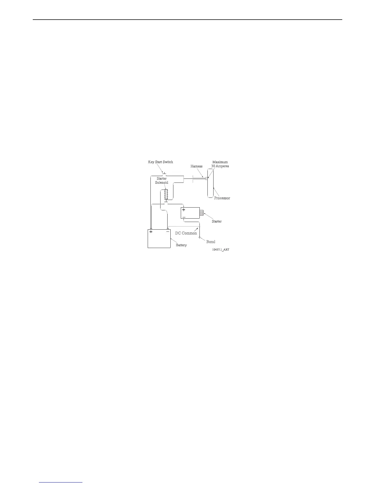
4.3.2.2 Start Interlock Cable
A Run the cable to the Engine’s Starter Solenoid.
B Disconnect the Starter Switch wire from the Solenoid.
C Strip back the appropriate amount of PVC jacketing and conductor insulation.
D Connect one of the conductors to the Solenoid’s Starter Switch terminal.
Figure 4-2: Start Interlock Connections
4.3.2.3 Butt splice the second wire to Starter Switch wire.
4.3.2.4 External Alarm Circuit Cable (optional)
Refer to Section Section 8.1: External Alarm Capability for installation information.
4.3.2.5 Clutch Pressure Switch Cable (optional)
Refer to Section Section 8.2: Clutch Pressure Interlock, for installation information.
Key Start Switch
Maximum
30 Amperes
Starter
Solenoid
Processor
Starter
+
_
DC Common
Bond
Battery
+
_
10457.1_ART
Harness

 Loading...