F The measurement should be 0 VDC and the adjacent LED should not be lit.
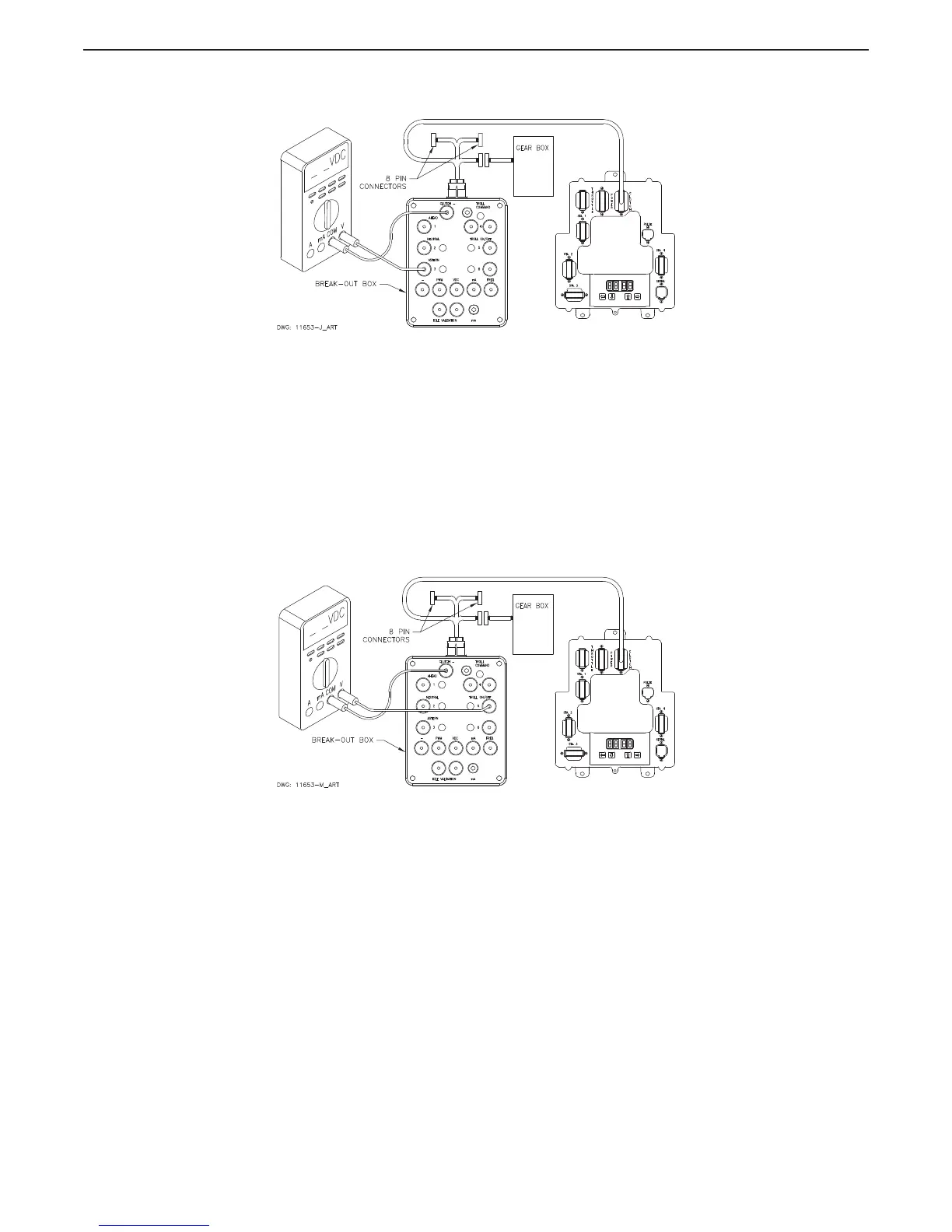
Figure MM13927-11: Clutch Connections Astern Solenoid
G Position the Control Head lever into the Astern detent. The measurement should be 12 or 24
VDC depending on the Astern Solenoid’s rating. The LED adjacent to the Astern plug on the
Break-out Box should be lit. Return the Control Head lever to the Neutral/Idle position.
2.3 Troll Testing
2.3.1 Troll On/Off Solenoid
A Ensure power is removed from both the Processor and the Clutch Power Supply.
B Disconnect the Clutch Harness from the number 3 Processor connector/pigtail.
C Insert the Break-out Box between the number 3 Processor connector/pigtail and the Clutch
Harness as shown in Figure MM13927-12: Troll Connections Troll On/Off Solenoid.
Figure MM13927-12: Troll Connections Troll On/Off Solenoid
D Set up the Multimeter to measure DC Volts and connect the black lead to the socket labeled
“CLUTCH –” and the red lead to the socket labeled “TROLL ON/OFF” as shown in Figure
MM13927-12: Troll Connections Troll On/Off Solenoid.
E Turn power ‘On’ to the Processor and the Clutch Power Supply and take command at a
Remote Station with the Control Head lever in the Neutral/Idle position.
F Depress the Transfer Button again for approximately 2 seconds until the red LED begins
blinking at a fast rate (Troll Mode Indication).

 Loading...