5.7.2.1.6 Function Code L3 – Solenoid Troll Maximum Pressure
This Section along with the Basic Troll Command Functions allows the adjustment of the
Processor’s Solenoid Integrated Troll command.
Function L3 fine tunes the amount of current delivered to the proportional solenoid, so that
clutch pressure is at the maximum point prior to Clutch Plate lock-up.
The hydraulic pressure on the Clutch plate can typically be decreased to a point where the
shaft is rotating at approximately 70% of normal shaft RPM at Idle. Attempts to increase
pressure above this point typically results in Clutch Plate lock-up.
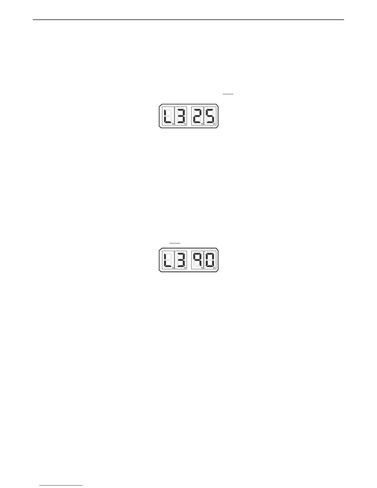
The available Values are 20.0 to 100.0 percent of the maximum current available. The
Default Value is 25.0%. The Value selected must
be at least 20% above or below (Normal/
Inverse) the Troll Minimum Pressure L2 selected.
Figure 5-53: Display LED Solenoid Function L3 Set Up Activated
A Move the Control Head lever to the Ahead detent.
B Scroll to Function Code.
C Activate Set Up Mode.
D Scroll Up or Down to the appropriate Value.
E Store the Value to memory
5.7.2.1.7 Function Code L3 – Servo Troll Maximum Pressure
This Section along with the Basic Troll Command Functions allows the adjustment of the
Processor’s Servo Troll command.
This Function adjusts the Troll Push-Pull cable travel to the point where clutch pressure is at
the maximum point, yet not quite at normal shaft RPM at Idle.
The hydraulic pressure on the Clutch plate can typically be decreased to a point where the
shaft is rotating at approximately 70% of normal shaft RPM at Idle.
The available Values are 20.0 to 100.0 percent of the 3.00 inches (76,2mm) of Troll Push-
Pull cable travel.
The Default Value is 90.0%.
The Value selected must
be at least 10% above the Troll Minimum Pressure L2 selected.
Figure 5-54: Display LED Servo Function L3 Set Up Activated
A Move the Control Head lever to the Ahead detent.
B Scroll to Function Code.
C Activate Set Up Mode.
D Scroll Up or Down to the appropriate Value.
E Store the Value to memory

 Loading...