B Depressing either the Up or Down Arrow Push Button will activate the Function Menu. (refer to
Figure MMC-343-11: Display Function Menu Activated)
C Depressing either the Up or Down Arrow Push Button will scroll through the Function Menu one at a
time.
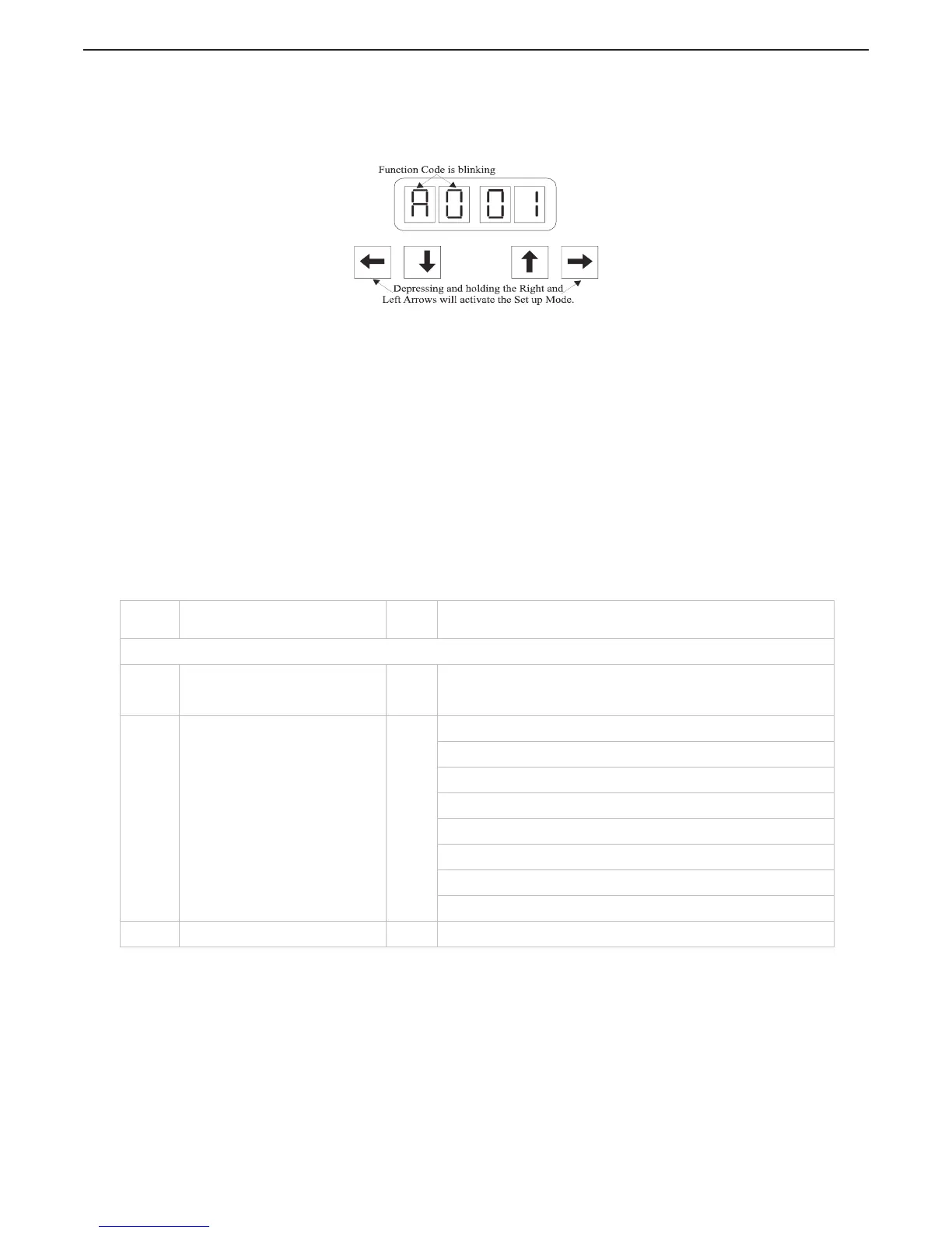
Figure MMC-343-12: Display with Set up Activated
D Once the desired Function Code is visible on the Display, depressing and holding the Left and Right
Arrow Push Buttons at the same time will activate Set Up. The left two Display pads will begin to
blink, indicating that the value is ready to be changed. Refer to Figure MMC-343-12: Display with
Set up Activated
E Depressing either the Up or Down arrow push buttons will change the Value of the Function.
Holding down either the Up or Down arrow push buttons will scroll quickly through the values.
F When the value required is displayed, depress and hold the Right and Left Arrow push buttons until
the Display Function Code stops blinking and becomes solid. The new Value is now set into
memory.
G Depressing either the Up or Down arrow push buttons will now scroll through the Function Codes.
MMC-343: 10 Set Up Functions & Values
The following table lists the various Function Codes, the Function’s Name, Default Value and Range. Each
Function will be explained in one of the following Sections.
Table MMC-343-1: Functions List
Function
Code
Function Name
Default
Value
Value Range or Options
STATION EXPANDER FUNCTIONS
A0 Station Expander Identification 01
01, 02, 03, 04, 05 (Must match Processor Identification set in the
9000 Series / CruiseCommand Processor the Expander is connected
to.)
H0 Diagnostic 00
Input Voltage (+/- 0.5VDC)
Tachometer Sensor Frequency
Station 1 Lever A/D
Station 2 Lever A/D
Station 3 Lever A/D
Station 4 Lever A/D
Transfer Button, Stations 1, 2, 3 & 4
Software Revision Level
H1 Erase EPROM 00 Store to Erase (For Authorized Personnel Only)

 Loading...