5.7.1.3.3 Function Code C7 – ZF-Hurth Duty Cycle Astern
This function limits the amount of current delivered to the Astern Proportional Solenoid.
Failure to limit the current may result in permanent damage to the solenoid.
The available Values are 00.0 to 100.0 percent Duty Cycle of the applied voltage.
The Default Value is 100%.
To determine, and if required, change the Value (Refer to Sections Section 5.2: Activating
Set Up Mode and Section 5.3: Storing Values To Memory):
A Ensure that Troll is not
selected (no rapidly blinking LED).
B Connect an amp meter in series with the Astern solenoid signal.
C Move the Control Head lever to the Astern detent.
D Scroll to Function Code C7.
E Activate Set Up Mode.
F Scroll Up or Down until the appropriate minimum current level is reached.
G Store the Value to memory.
H Return the Control Head lever to the Neutral/Idle position.
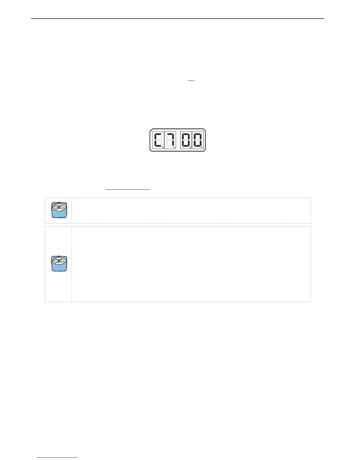
Figure 5-43: Display LED Function C7 Set Up Activated
5.7.2 Troll Functions
5.7.2.1 Basic Troll Command Functions
The Basic Troll Functions
that are common on all Processors with Trolling Valve control is L0, L4, and
L5.
5.7.2.1.1 Function Code L0 – Troll Enable and Control Head Lever Troll Range
This Function Code tells the Processor whether or not:
• A 9001 Trolling Actuator or integrated Troll Control exists.
• How the trolling valve is to be controlled.
There are four types which can be used to control any trolling valve.
How these different Types function and when and where they may be applied is described
in the Trolling Actuator’s Installation Manual for the 9001 Trolling Actuator and in Section
2.4: Start Interlock (if used) for Integrated Troll Control.
NOTE: All Troll Functions other than L0 will not be displayed on the Processor Display LED if Function L0 is set
to 00. To utilize Troll and display the rest of the Troll Functions, a value other than 00 needs to be entered for
Function L0.
NOTE: If the Control System does not offer integrated Troll control, a 9001 Troll Actuator is required to offer
Trolling Valve Control.
Integrated Troll Control
All Troll Functions other than L0 will not be displayed on the Processor Display LED if Function L0 is set to 00.
To utilize Troll and display the rest of the Troll Functions, a value other than 00 needs to be entered for Function
L0.
9001 Troll Actuator
All the Function Codes relating to Troll will not be displayed, unless an external Troll Actuator (p/n 9001) is
connected to the Processor. Installation and adjustment details are included with the Troll Actuator.
The following is a brief outline of the Basic Troll Function adjustments.

 Loading...