5.7.2.1.2 Troll Solenoid L1 Function
This Section along with the Basic Troll Command Functions allows the adjustment of the
Processor’s Integrated Troll command.
Function Code L1 presets the profile and the amount of current delivered to the Trolling
Valve’s proportional solenoid.
The Values for this Function are listed below:
00 - Normal, No Current when at Lock-up
01 - Inverse, No Current when at Lock-up
02 - Normal, Maximum Current when at Lock-up. Preset for ZF220-550,
12VDC Systems.
03 - Normal, No Current when at Lock-up. Preset for ZF220-550, 24VDC
Systems.
04 - Normal, No Current when at Lock-up. Preset for ZF2000, 24 VDC
Systems.
05 - Inverse, No Current when at Lock-up. Preset for ZF670, 1900 or 2500,
24VDC Systems.
06 - Preset for 12VDC ZF Hurth Systems.
07 - Preset for 24VDC ZF Hurth Systems.
The default value is 00.
To determine, and if required, change the Value (Refer to Sections Section 5.2: Activating
Set Up Mode and Section 5.3: Storing Values To Memory):
A Scroll to Function Code L1.
B Activate Set Up Mode.
C Scroll Up or Down to the appropriate Value for the Trolling Valve.
D Store the Value to memory
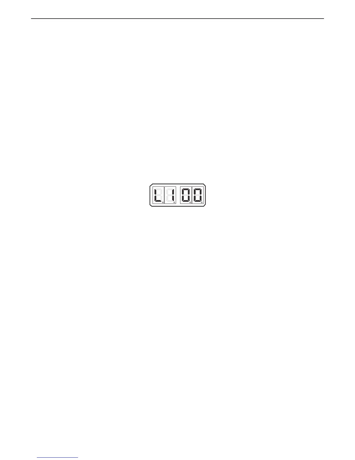
Figure 5-49: Display LED Function L1 Set Up Activated
5.7.2.1.3 Troll Servo L1 Function
L1 – Troll Servo Direction
This section along with the Basic Troll Functions allows the adjustment of the Processor’s
Integrated Servo Troll command.
This Function Code determines whether the Troll Push-Pull cable is fully extended or
retracted when at Lock-up.
The available Values are:
20 Lock-up – Push-Pull cable fully retracted. (Default Value)
21 Lock-up – Push-Pull cable fully extended.
To determine, and if required, change the Value (Refer to Sections Section 5.2: Activating
Set Up Mode and Section 5.3: Storing Values To Memory):
A Move the Troll Selector Lever to the Lock-up (Full Pressure) position.
B Check to see if the Push-Pull cable’s ball joint are in close proximity to one
another.
• If so, no adjustments of Function Code L1 Troll Servo Direction
are required.
• If they are not, continue with the next step.
C Scroll to Function Code L1.
D Activate Set Up Mode.
E Scroll Up or Down to Value 20 or 21.

 Loading...