10.3.3 Component Condition
10.3.3.1 Control Heads
Inspect for any signs of corrosion due to water incursion. If hard-wired, ensure that all the fork
connectors are properly secured to the terminal. Verify all wires are fully crimped and do not pull loose.
10.3.3.2 Processors
Inspect the Processor for any signs of physical damage.
10.3.4 Interconnecting Wiring and Harnesses
A Inspect the wire terminations for loose connections, corrosion or wire strands.
B Inspect the Harness’s pins and sockets for bent pins, torn boots or any signs of corrosion.
The first step in troubleshooting a problem with the Propulsion System is to determine if the problem
is with the Control System or something external to the System. In all cases a Control System
malfunction will alert the operator of the potential problem. This is accomplished through the audible
tone emitted at all Remote Stations. When an audible tone is emitted, it will be accompanied by an
Error Message at the Processor. Also, in many cases, the Control System will alert the operator to a
problem external to the Control System.
The following are examples of components both internal and external to the Control System which
could be a source of trouble:
The following pages should give you a good guideline for making this determination. There is no need
to troubleshoot the system to any point further than one of the main components listed above. If the
fault is found to be with a Control System component, that component is simply replaced. If the fault
is found to be with one of the external components, replace or repair the defective component or
contact a qualified mechanic.
10.4 Troubleshooting Diagnostic Menu
The Processor has built in diagnostics designed to assist the technician in determining the cause of a
problem. The following information is available to view at any time:
• Applied Battery Voltage
• Tachometer Sender Frequency
• Stations 1- 5 A/D’s
• Stations 1- 5 Transfer Button Status
• Servo 2 Feedback A/D’s
• Servo 1 Feedback A/D’s
• Software Revision Level
In order to access this information, follow the steps below:
A Locate the Display LED on the Port or Starboard Processor. The Display LED will have the Processor
Part Number displayed in a running pattern moving from left to right while the program is running in
Normal Operation.
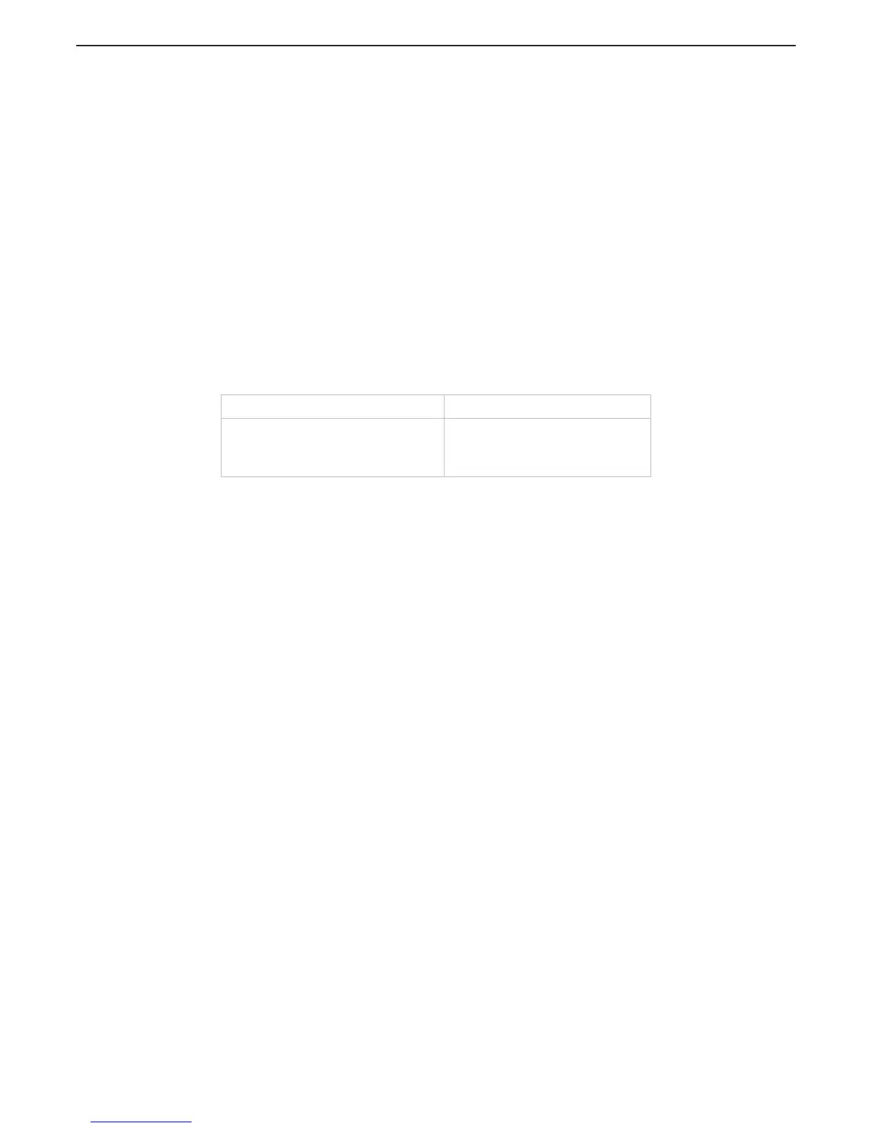
Table 10-2: Examples of Components (Internal/External)
Internal External
1) Processor
2) Control Head
3) Interconnecting Wiring (Harnesses)
4) Push-Pull Cable
1) DC Power Source
2) Engine
3) Transmission
4) Push-Pull Cable

 Loading...