Home
ZF
Computer Hardware
MM9000
ZF MM9000 User Manual
5
of 1
of 1 rating
332 pages
Give review
Manual
Specs
To Next Page
To Next Page
To Previous Page
To Previous Page
Loading...
181
EN 3340.758.003a - 2014-11
TROUBLESHOOTING
M
M
90
00
Re
v
C.
8
0
1
/1
3
P
age
18
1
M
M
9
0
0
0
Cl
e
a
r
C
o
m
m
a
n
d
Us
e
r
M
a
n
u
a
l
T
r
o
ubl
e
sh
o
o
t
i
ng
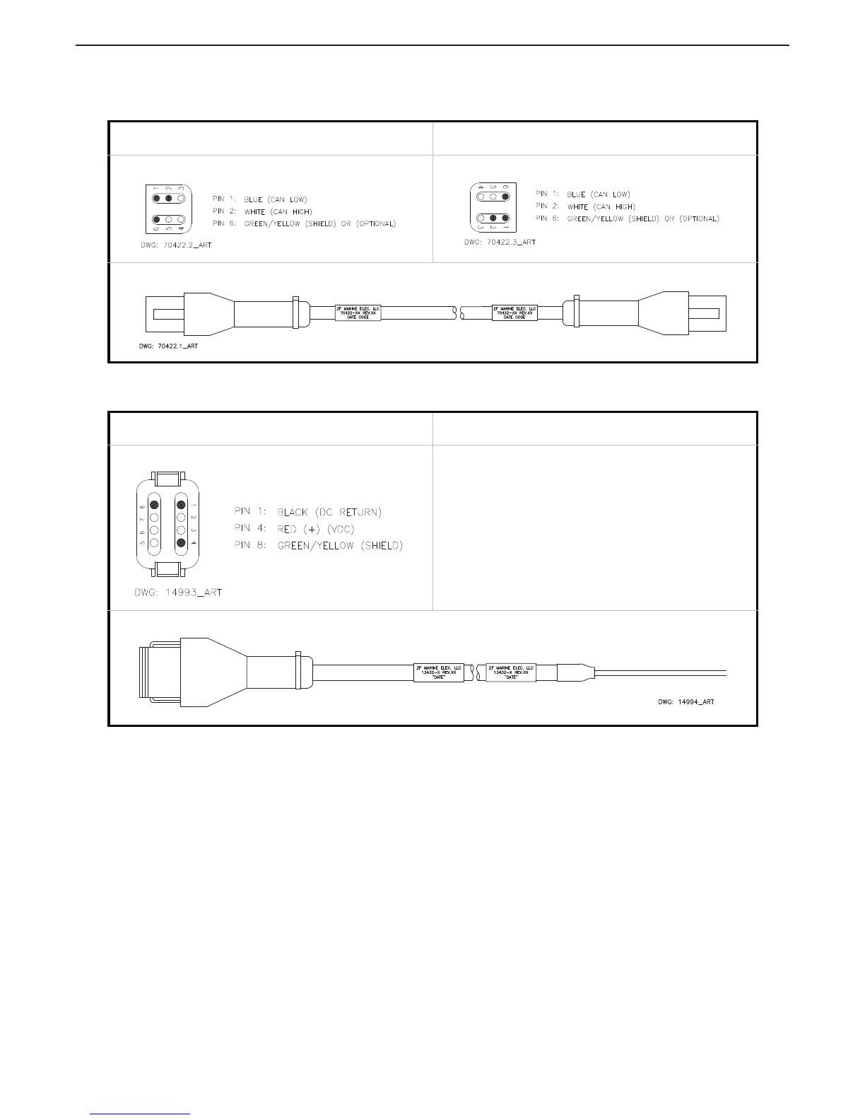
10.12.1.2
Throttle Wire Harnesses
T
able 10-16: Wire Harness - Serial Communication / CANtrak (p/n 70422-XX)
T
ermination A
T
ermination B
T
able 10-17: Wire Harness - Thr
ottle, V
oltage (IVECO, Cummins) (p/n 13432-XX)
T
ermination A
T
ermination B
N/A
180
182
Table of Contents
Table of Contents
3
Default Chapter
1
Clearcommand User Manual
1
Table of Contents
3
List of Figures
7
List of Figures
8
List of Figures
9
List of Figures
10
List of Tables
13
Revision List
15
Preface
17
Important Information
18
1 Introduction
21
Basic Theory of Operation
21
Figure 1-1: Basic 9120 or 9122 Clearcommand System Diagram
22
Figure 1-2: Basic 9121 Clearcommand System Diagram
23
Figure 1-3: Basic 9210 Clearcommand System Diagram
24
Figure 1-4: Basic 9211 Clearcommand System Diagram
25
System Features
26
Figure 1-5: Basic 9221 Clearcommand System Diagram
26
2 Operation
27
DC Power on
27
Taking Command
27
Figure 2-1: Station Taking Command
27
Basic Operation
28
Figure 2-2: Control Head Detents
28
Start Interlock (if Used)
29
Figure 2-4: Control Head 35 Degree Troll Range - Type 2
29
Figure 2-5: Control Head 45 Degree Troll Range - Type 3
29
Figure 2-6: Control Head 55 Degree Troll Range - Type 4
29
Station Transfer
30
Proportional Pause
30
Figure 2-7: Remote Stations before Transfer of Command
30
Figure 2-8: Remote Station Transfer after Transfer of Command
30
Warm-Up Mode
31
Figure 2-9: Control Head Warm-Up Mode
31
Figure 2-10: Control Head Normal Operating Mode
31
High/Low Idle
32
Figure 2-11: High/Low Idle Mode Selection
32
One Lever Mode (Twin Screw)
33
Figure 2-12: Step A) One Lever Operation Mode
33
Figure 2-13: Step B) One Lever Operation Mode
34
Engine Synchronization (Twin Screw)
35
2.11 Control System's Configurability
37
2.12 Audible Tones
39
2.13 Push Button Set up
41
2.14 Visual System Diagnostics, Set up and Status Indication
41
Figure 2-14: Circuit Board Shield Layout
41
2.15 Pluggable Connections
42
Figure 2-15: Standard Processor Pluggable Connections View
42
2.16 Optional Features Operation
43
3 Plan the Installation
45
System Requirements
45
Figure 3-1: Processor Dimensions
45
Installer Supplied Tools and Parts
50
DC Power Source
51
4 Installation
53
Processor
53
Control Head(S)
53
Wire Harness Installation
53
Figure 4-1: Harness Plug Keying
53
Figure 4-2: Start Interlock Connections
54
Figure 4-3: Twin Screw Serial Harness Connections
56
Hard-Wired Cable
58
Figure 4-4: Liquid Tight Installation
58
Figure 4-5: Standard Enclosure Cable Holes
58
Figure 4-6: Standard Circuit Board Hard-Wired Termination Points
59
Figure 4-7: 9120 and 9121 Enclosure Cable Holes
60
Table 4-1: Clearcommand Processor Optional Hard-Wiring Cable List
60
Figure 4-8: 9122 Enclosure Cable Holes
61
Figure 4-9: 9210 and 9211 Enclosure Cable Holes
62
Figure 4-10: 9221 Enclosure Cable Holes
63
Figure 4-11: 9000 Series Circuit Board Hard-Wired Termination Points
64
Figure 4-12: Seven-Conductor Control Head Cable Shield Wire and Heat-Shrink
65
Figure 4-13: Clamp Views
65
Figure 4-14: Terminal Strip Cable Connections
65
Figure 4-15: Two-Conductor Start Interlock Cable
66
Table 4-2: Processor Circuit Board Terminal Strip Color Coded Connections for Remote Stations
66
Figure 4-16: Two-Conductor Power Cable
67
Figure 4-17: Four-Conductor Serial Communication Cable
67
Figure 4-18: AC Type Tachometer Cable
68
Table 4-3: Processor Circuit Board Terminal Strip Color Coded Connections for Serial Communication
68
Figure 4-20: Clutch Cable Heat Shrink in Processor
69
Table 4-4: Processor Circuit Board Terminal Strip Color Coded Connections for Tachometer
69
Figure 4-21: Clutch Cable Plug Termination Connections
70
Figure 4-22: Clutch/Troll Cable Heat Shrink in Processor
70
Table 4-5: Clutch Termination Table
70
Figure 4-23: Clutch Cable Plug Termination Connections
71
Table 4-6: Clutch/Troll Termination Table
71
Figure 4-24: Clutch Cable Heat Shrink in Processor
72
Figure 4-25: Clutch Cable Plug Termination Connections
72
Table 4-7: Clutch Termination Table
72
Engine Stop Switches
73
Figure 4-26: Engine Shield
73
Table 4-8: Throttle Termination Table
73
Push-Pull Cable Connections
74
Figure 4-27: Processor Cable Clamp Rotation
74
Figure 4-28: Push-Pull Cable Interior Connection
74
Figure 4-29: Throttle Push-Pull Idle Orientation to Selector Lever
75
Figure 4-30: Shift Push-Pull Cable Neutral Connection at Transmission
75
5 Set up Procedure
77
Processor Components Used in Set up
77
Figure 5-1: Typical Processor Cover
77
Figure 5-2: Processor Shield Push Button and Display LED Locations
78
Figure 5-3: Display LED at Normal Operation
78
Figure 5-4: Display LED Designations
78
Figure 5-5: Circuit Board Push Buttons
79
Figure 5-6: Display LED Error Menu Example
79
Figure 5-7: Display LED Four Digit Value
79
Activating Set up Mode
80
Storing Values to Memory
80
Set up Function Codes and Values
80
Table 5-1: Function Codes
80
Table 5-2: Processors Function Code Defaults
83
Field Service Test Unit (Break-Out Box) and Multimeter Use
85
Figure 5-8: Service Field Test Unit and Multimeter
85
System Programming and Adjustments
86
Figure 5-9: E1, E2, E3, E4, E6, L4 Processor, Test Unit, and Multimeter Connections
86
Figure 5-10: L2, L3, C6, and C7 Processor, Test Unit, and Multimeter Connections
86
Figure 5-11: Display LED Function A0 Set up Activated
87
Figure 5-12: Display LED Function A1 Set up Activated
88
Figure 5-13: Display LED Function A2 Set up Activated
88
Figure 5-14: Display LED Function A3 Set up Activated
89
Figure 5-15: Display LED Function A4 Set up Activated
89
Figure 5-16: Display LED Function E5 Set up Activated
90
Figure 5-17: Display LED Function E6 Set up Activated
90
Function Code E1 - Throttle in Neutral
91
Figure 5-18: Display LED Function E1 Set up Activated
91
Figure 5-19: Display LED Function E4 Set up Activated
91
Figure 5-20: Display LED Function E7 Set up Activated
92
Figure 5-21: Throttle Push-Pull Cable Orientation
92
Figure 5-22: Example: Throttle Push-Pull Cable Fully Retracted Position for Idle
93
Figure 5-23: Display LED Function E0 Set up Activated
93
Figure 5-24: Display LED Function E2 Set up Activated
93
Figure 5-25: Throttle Push-Pull Cable Full Throttle Position
94
Figure 5-26: Display LED Function E3 Set up Activated
94
Figure 5-27: Display LED Function E0 Set up Activated
95
Figure 5-28: Display LED Function E2 Set up Activated
95
Figure 5-29: Display LED Function E3 Set up Activated
96
Figure 5-30: Display LED Function C0 Set up Activated
96
Figure 5-31: Display LED Function C1 Set up Activated
97
Figure 5-32: Display LED Function C2 Set up Activated
97
Figure 5-33: Display LED Function C3 Set up Activated
98
Figure 5-34: Display LED Function C4 Set up Activated
99
Figure 5-35: Clutch Push-Pull Cable Orientation
100
Figure 5-36: Display LED Function C5 Set up Activated
100
Figure 5-37: Clutch Push-Pull Cable Ahead Position
101
Figure 5-38: Display LED Function C6 Set up Activated
101
Figure 5-39: Clutch Push-Pull Cable Astern Position
102
Figure 5-40: Display LED Function C7 Set up Activated
102
Figure 5-41: Display LED Function C5 Set up Activated
103
Figure 5-42: Display LED Function C6 Set up Activated
103
Figure 5-43: Display LED Function C7 Set up Activated
104
Figure 5-44: Display LED Function L0 Set up Activated
105
Figure 5-45: Control Head 20 Degree Troll Range - Type 1
105
Figure 5-46: Control Head 35 Degree Troll Range - Type 2
105
Figure 5-47: Control Head 45 Degree Troll Range - Type 3
105
Figure 5-48: Control Head 55 Degree Troll Range - Type 4
105
Figure 5-49: Display LED Function L1 Set up Activated
106
Figure 5-50: Display LED Function L1 Set up Activated
107
Figure 5-51: Display LED Solenoid Function L2 Set up Activated
107
Figure 5-52: Display LED Servo Function L2 Set up Activated
107
Figure 5-53: Display LED Solenoid Function L3 Set up Activated
108
Figure 5-54: Display LED Servo Function L3 Set up Activated
108
Figure 5-55: Display LED Solenoid Function L4 Set up Activated
109
Figure 5-56: Display LED Function L6 Set up Activated
110
Figure 5-57: Display LED Function L6 Set up Activated
110
Table 5-3: Solenoid Error Status Enable
111
6 Dock Trials
113
Control Heads (Engines Stopped)
113
Start Interlock (Engines Stopped)
113
Engine Stop Switches
113
Push-Pull Cables
113
High Idle
114
Control Head Servo Command
114
Control Head Solenoid Command
114
Throttle Pause Following Servo Shift
114
Throttle Pause Following Solenoid Shift
114
6.10 Trolling Valve
115
Table 6-1: Shaft RPM at Idle
115
Table 6-2: Shaft RPM at Idle
116
7 Sea Trials
117
Full Speed Setting - Servo Throttle
117
Full Speed Setting - Electronic Throttle
117
Proportional Pause
117
Synchronization Test (Twin Screw Only)
119
Table 7-1: Shaft RPM at Idle
120
Table 7-2: Troll Valve Adjustments
121
Sea Trial Report
124
9000 Series Sea Trial Report
125
Table F-226-1: Vessel Information
125
Table F-226-2: Processor Information
125
Table F-226-3: Power Supply
126
Table F-226-4: Dock Trials
126
Table F-226-5: Record at Dock
126
Table F-226-6: Sea Trials
127
Table F-226-7: Record During Sea Trial
127
Table F-226-8: Processor Parameters Record
127
8 Control Options
131
External Alarm Capability
131
Figure 8-1: External Alarm Connections Processor Hard-Wired Example
131
Figure 8-2: External Alarm Connections Processor Hard-Wired Example
131
Clutch Pressure Interlock
132
Figure 8-3: Clutch Pressure Switch with Processor Harness Diagram
133
Figure 8-4: Clutch Pressure Switch with Processor Hard-Wired Diagram
133
Station Expander (SE)
134
9001 Actuator Trolling Valve Control
134
9 Periodic Checks and Maintenance
135
Control Heads
135
Processor
135
Power Supply
135
Table 9-1: Fully Charged Battery
136
10 Troubleshooting
137
General
137
Figure 10-1: 9120 and 9122 Basic Twin Screw, Two Station Diagram
137
Figure 10-2: 9121 Basic Twin Screw, Two Station Diagram
138
Figure 10-3: 9210 Basic Twin Screw, Two Station Diagram
139
Figure 10-4: 9211 Basic Twin Screw, Two Station Diagram
140
Figure 10-5: 9221 Basic Twin Screw, Two Station Diagram
141
Table 10-1: Clearcommand Processor Push-Pull Reference
142
Troubleshooting Questions
143
Troubleshooting Problem Resolution
144
Troubleshooting Diagnostic Menu
145
Table 10-2: Examples of Components (Internal/External)
145
Figure 10-6: Display Function Code List
146
Figure 10-7: Display Troubleshooting Function
146
Figure 10-8: Display Troubleshooting Function Blinking
146
Figure 10-9: Example Display of Applied Battery Voltage
146
Figure 10-10: Example Display of Tach Sensor Frequency
146
Figure 10-11: Example Display Control Head Lever Current Positions
147
Figure 10-12: Example Display Control Head Transfer Button Status View
147
Figure 10-13: Example Display Software Revision Level View
147
Troubleshooting Audible Tones
148
Figure 10-14: Display Examples of Remote Stations
149
Figure 10-15: Display Examples of Remote Stations A/D Value
150
Troubleshooting Station Transfer
154
Figure 10-16: Display Station A/D's no Station Transfer Button Depressed
155
Figure 10-17: Example Display Station A/D's Transfer Button Depressed for Stations 1 - 4
155
Figure 10-18: Display Station A/D/S Transfer Button Depressed for Station 5
155
Table 10-3: Control Head Lever A/D Counts
155
Troubleshooting Stuck Transfer Button
156
Error Codes
156
Table 10-4: Clutch Solenoid Control System Error Codes
156
Table 10-5: Troll Solenoid Control System Error Codes
156
Table 10-6: Basic Control System Error Codes
157
Table 10-7: Servo 1 Error Codes
159
Table 10-8: Servo 2 Error Codes
159
Basic Problem Causes and Solutions
160
Table 10-9: Basic Control System Problem Causes and Solutions
160
Table 10-10: Servo 2 Throttle Problem Causes and Solutions
169
Table 10-11: Servo 1 Clutch Problem Causes and Solutions
169
Table 10-12: Servo 2 Troll Problem Causes and Solutions
170
Table 10-13: Servo 2 Troll Problem Causes and Solutions
171
10.10 Problems Without Error Codes
172
10.11 Synchronization Troubleshooting
175
10.12 Troubleshooting Wire Harnesses
179
Table 10-14: Wire Harness - Serial Communication (P/N 13316-XX)
179
Table 10-15: Wire Harness - Serial Communication Multi-Screw (P/N 15544-XX)
180
Table 10-16: Wire Harness - Serial Communication / Cantrak (P/N 70422-XX)
181
Table 10-17: Wire Harness - Throttle, Voltage (IVECO, Cummins) (P/N 13432-XX)
181
Table 10-18: Wire Harness- Throttle, Current (MAN, MTU) (P/N 13494-XX)
182
Table 10-19: Wire Harness - Throttle, Voltage (Cummins Plug), (P/N 13565-XX)
182
Table 10-20: Voltage Throttle Harness Pin-Out (P/N 14148-XX)
183
Table 10-21: Wire Harness - Throttle (Pulse Width Modulation [PWM]), (P/N 13533-XX)
183
Table 10-22: Voltage Throttle Harness Pin-Out (P/N 71262-XX)
184
Table 10-23: Cable, Throttle, man EDC (P/N 14421-XX)
184
Table 10-24: Wire Harness - Throttle Current W/ Mag Pickup, man (Non-Common Rail) (P/N 14363-XX)
185
Table 10-25: Wire Harness - Clutch, Ahead, Astern (P/N 15719-XX)
186
Table 10-26: Wire Harness - Ahead / Astern Troll On/Off Command (P/N 15725-XX)
186
Table 10-27: Wire Harness - Clutch with Troll Command (P/N 15732-XX)
187
Table 10-28: Wire Harness- Clutch, Ahead, Astern, Troll Command, Troll On-Off (P/N 70390-XX)
188
Table 10-29: Wire Harness- Clutch, Ahead, Astern, ZFF Transmission (P/N 70673-XX)
189
Table 10-30: Power, Start Interlock Harness Pin-Out (P/N 13756-XX)
189
Table 10-31: Wire Harness - Power, si & Clutch Pressure Switch (P/N 13552-XX)
190
Table 10-32: Wire Harness - Power, SI, Clutch Pressure Switch & Alarm (P/N 13631-XX)
190
Table 10-33: Wire Harness- Power Use W/Existing St Intlk Only (P/N 15023-XX)
191
Table 10-34: Wire Harness - Control Head One Connector (P/N 13557-XX)
191
Table 10-35: Wire Harness - Control Head Two Connectors (P/N 14261-XX)
192
10.13 Processor Pigtails
193
Table 10-36: Wire Harness - Serial Communication, Processor Lead (P/N 15705-XX)
193
Table 10-37: Wire Harness - Throttle, Processor Lead (P/N 15703-XX)
194
Table 10-38: Wire Harness - Solenoid Clutches, Processor Lead (P/N 15701-XX)
194
Table 10-39: Power, Start Interlock, Clutch Oil Pressure Switch, and Alarm Pigtail Pin-Out (P/N 15710-XX)
195
Table 10-40: Wire Harness - Control Head, Processor Lead (P/N 15706-XX)
196
Table 10-41: Wire Harness - Mag Pickup, Processor Lead (P/N 15704-XX)
196
11 Appendix A - System Components and Specifications
197
MMC-280 400 Series Control Head Variations
199
Figure MMC-280-1: Part Numbering Configurations
199
Figure MMC-280-2: Detents Available
199
Figure MMC-280-3: Dimensions
200
Figure MMC-280-4: Terminal Connections
201
Figure MMC-280-5: AFT Facing Control Head
201
MMC-329 MC2000 Series Standard Control Head Variations
205
Figure MMC-329-1: Part Numbering Configurations Detents Available
205
Figure MMC-329-2: Dimensions
206
Figure MMC-329-3: Terminal Connections
207
Figure MMC-329-4: AFT Facing Control Head
207
MMC-307 700 Series Standard Control Head Variations
209
Figure MMC-307-1: Part Numbering Configurations
209
Figure MMC-307-2: Detents Available
209
Figure MMC-307-3: Dimensions
209
Figure MMC-307-4: Dual Control Head Connections
211
Figure MMC-307-5: Aft Facing Control Head
211
MMC-279 400 Series Weather Mount Enclosure
215
Deutsch Connector Assembly
217
S-214 Automatic Power Selector Model: 13505
219
Drawing 11488 DC Power Source Kit
221
Grounding (Bonding)
231
MMC-288 References and Parts Source
233
SER-161 Engine Tach Sender Req
235
MMC-289 Morse Clutch and Throttle Kit
237
Universal Mounting Kit
239
43C Cable Conversion Kit
241
Appendix A - System Components and Specifications
243
Default Chapter
243
MMC-343 Station Expander User Instructions
243
Figure MMC-343-1: Station Expander
244
MMC-343 Station Expander User Instructions
244
MMC-343: 1 Features
244
MMC-343: 2 Required Parts
244
MMC-343: 3 Location
244
MMC-343: 4 Station Expander Power
245
MMC-343: 5 Harnesses
245
Figure MMC-343-2: Station Expander Harness Connector Locations
246
Figure MMC-343-3: Harness Plug Connectors
246
MMC-343: 6 Tools for Installation
246
Optional
246
Required
246
Figure MMC-343-4: Station Expander Dimensions
247
MMC-343: 7 Installation
247
Station Expander
247
Control Head Harnesses
248
Control Heads
248
Engine Stop Switch
248
Power Cable
248
Figure MMC-343-5: Station Expander Display LED and Arrow Push Buttons
249
MMC-343: 8 Set up Procedures
249
Station Expander Components Used in Set up
249
Figure MMC-343-6: Display LED at Normal Operation
250
Figure MMC-343-7: Display LED Designations
250
Push Buttons
250
Station Expander Display LED
250
Figure MMC-343-10: Display Normal Operating Condition
251
Figure MMC-343-8: Error Menu Example
251
Figure MMC-343-9: Display LED Four Digit Value
251
MMC-343: 9 Activating Set up Mode and Storing a Value
251
Figure MMC-343-11: Display Function Menu Activated
252
Figure MMC-343-12: Display with Set up Activated
252
MMC-343: 10 Set up Functions & Values
252
Table MMC-343-1: Functions List
252
A0 - Station Expander Identification
253
Control Head (Engines Stopped)
253
Figure MMC-343-13: Display with A0 - Station Expander Identification Set up Activated
253
H0 - Diagnostic
253
H1 - Erase EPROM
253
MMC-343: 11 Dock Trials
253
Table MMC-343-2: Troubleshooting Functions
253
Engine Stop Switches Test (Engines Running)
254
MMC-343: 12 Periodic Checks and Maintenance
254
Control Head
254
Station Expander
254
MMC-343: 13 Parts List
255
Cable (Electric)
255
Control Heads
255
Test Unit
256
Wire Harness (Plug)
256
12 Appendix B - QFA & DVTP
257
9000 Series Micro/Clearcommand Servo Throttle - Servo Clutch Qualitative Failure Analysis, Design Verification Test Procedure and Periodic Safety Test
259
9000 Series Clearcommand Throttle - Solenoid Clutch Qualitative Failure Analysis, Design Verification Test Procedure and Periodic Safety Test
263
9000 Series Electronic Throttle - Servo Clutch Qualitative Failure Analysis, Design Verification Test Procedure and Periodic Safety Test
267
9000 Series Servo Throttle - Solenoid Clutch, Qualitative Failure Analysis & Design Verification Test Procedure
271
13 Appendix C - Sales and Service Information
275
Factory Authorized Sales & Service - North America
277
Factory Authorized Service Centers - North America
283
Factory Authorized Sales & Service Centers - International
295
MMC-165 Warranty
303
Warranty Registration
305
MM13927 Field Service Test Unit
307
Figure MM13927-1: .Service Field Test Unit (Break-Out Box)
311
Figure MM13927-2: Cruisecommand Connector Locations
311
Figure MM13927-3: Example of Clearcommand Pigtail Locations
312
Figure MM13927-4: Throttle Connection (DC Voltage)
313
Figure MM13927-5: Throttle Connection (Current Ma)
314
Figure MM13927-6: Throttle Connection (PWM with DC Voltmeter)
315
Figure MM13927-7: Throttle Connection (PWM with Duty Cycle Meter)
316
Figure MM13927-8: Throttle Connection (Frequency Hz)
317
Figure MM13927-9: Clutch Connections Neutral Solenoid
317
Figure MM13927-10: Clutch Connections Ahead Solenoid
318
Figure MM13927-11: Clutch Connections Astern Solenoid
319
Figure MM13927-12: Troll Connections Troll On/Off Solenoid
319
Figure MM13927-13: Troll Connections (Proportional Solenoid)
320
Figure MM13927-14: 2-Speed Connections
321
Parts List
322
14 Appendix D - System Drawings
323
Drawing 12284 Clearcommand All Configuration Twin Screw System Drawing
325
5
Based on 1 rating
Ask a question
Give review
Questions and Answers:
Need help?
Do you have a question about the ZF MM9000 and is the answer not in the manual?
Ask a question
ZF MM9000 Specifications
General
Brand
ZF
Model
MM9000
Category
Computer Hardware
Language
English
Related product manuals
ZF CruiseCommand 785CE
160 pages

 Loading...