E Secure the Serial Harness at least every 18 in. (45,72 cm).
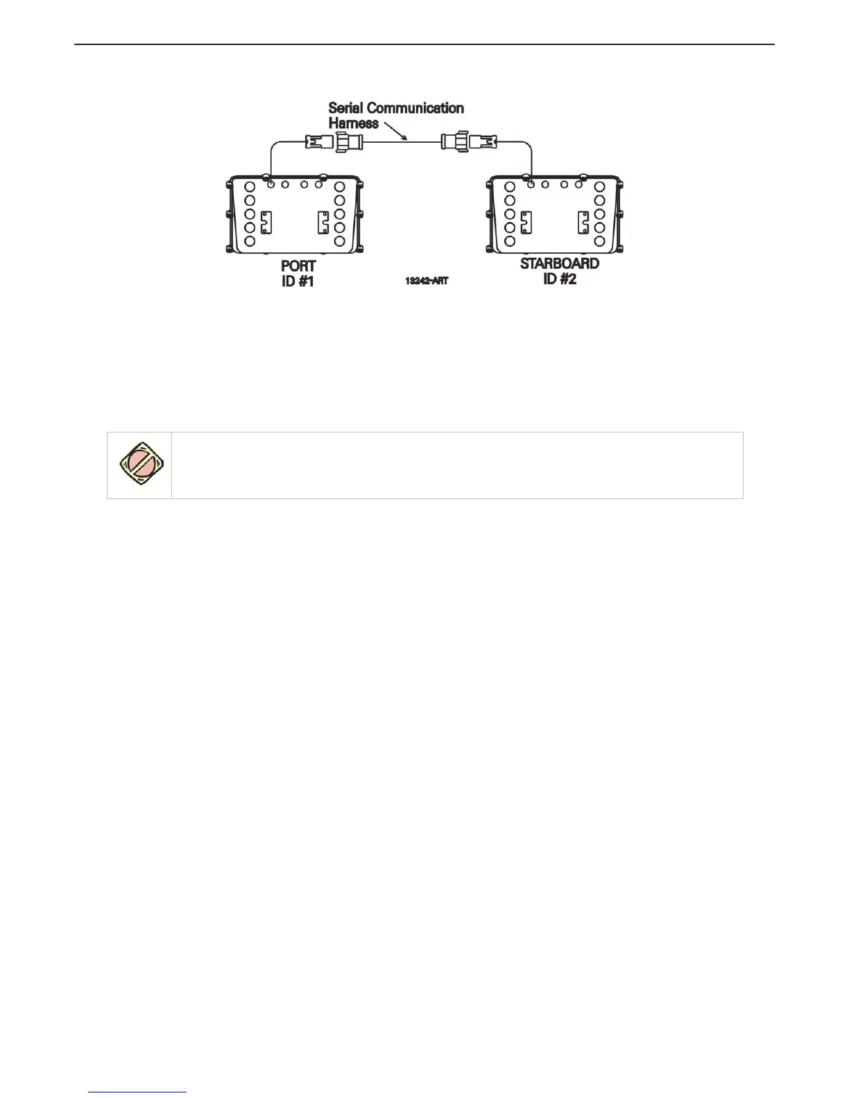
Figure 4-3: Twin Screw Serial Harness Connections
4.3.5 Tach Sensor Harness (required for Active Synchronization)
A At the Processors, remove the watertight seals from the Tach Sender pigtail plugs.
B At the Port Processor, insert the grey, four pin plug into the Tach Sender pigtail plug.
C Run the cable to the source of the Tach signal.
D Connect the conductors to the Tach source in the appropriate manner, keeping in mind that
some sources are polarity sensitive. (black- negative, red- positive)
E Repeat steps A) thru C) on the Starboard side.
4.3.6 Additional 9000 Series Harnesses
4.3.6.1 Throttle Harness
The appropriate Throttle Harness should have been selected in Section Section 3.1.5.1: Throttle
Harness. The Processors Throttle pigtail connects directly to the engine interface using this Throttle
Wire Harness.
A Connect the plug end of the Harness into the Throttle pigtail connector at the Processor.
B Run the cable to the engine interface.
C Refer to the engine documentation for termination points at the engine interface.
D If Twin Screw, repeat steps A) thru C) on the opposite side.
CAUTION: Electro-static discharge can damage this equipment. Whenever the Cover is removed, you must be
grounded to the chassis with the Anti-static Wrist Strap provided. Failure to do so may cause permanent
damage to the electronic circuits.

 Loading...