05 Quint Screw
To change the Value (Refer to Sections Section 5.2: Activating Set Up Mode and Section 5.3: Storing
Values To Memory):
A Scroll to Function Code A1.
B Activate Set Up Mode.
C Scroll Up or Down to the desired Value.
D Store the Value to memory.
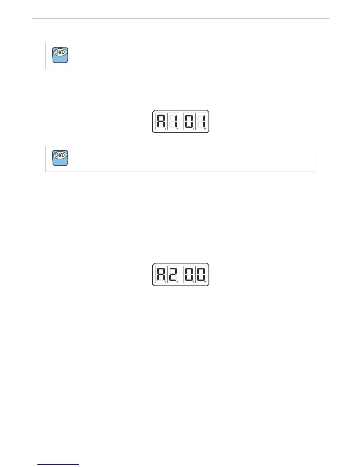
Figure 5-12: Display LED Function A1 Set Up Activated
5.6.1.3 Function Code A2 – One Lever Operation
In Twin Screw or more applications, the System has the ability to command all engines and
transmissions to the same speed and direction with a single Control Head lever. This Function allows
this Feature to be enabled or disabled. (Refer to Section 2.9: One Lever Mode (Twin Screw) for
operation instructions)
The available Values for this Function are:
00 Disabled (Default Value)
01 Enabled
To change the Value (Refer to Sections Section 5.2: Activating Set Up Mode and Section 5.3: Storing
Values To Memory):
A Scroll to Function Code A2.
B Activate Set Up Mode.
C Scroll Up or Down to the desired Value.
D Store the Value to memory.
Figure 5-13: Display LED Function A2 Set Up Activated
NOTE: Twin screw or more applications require Function Code A1 Values changed on all Processors prior to
changing the Value of Function Code A0.
NOTE: Before continuing set up, wait 5 minutes or cycle power.

 Loading...