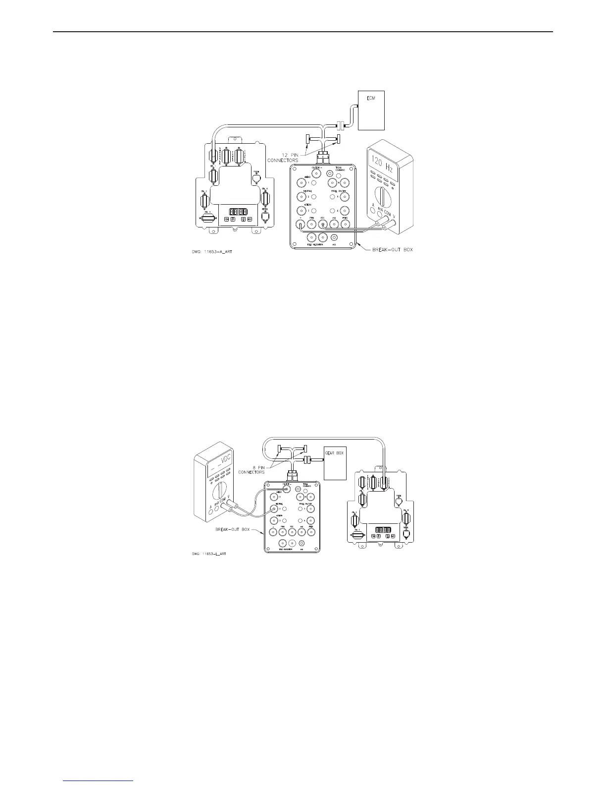
D Set up the Multimeter to measure Frequency and plug the black lead into the Break-out Box
black socket labeled “-” and the red lead into the socket labeled “FREQ”.
Figure MM13927-8: Throttle Connection (Frequency Hz)
E Turn power ‘On’ to the Processor and take command at any Remote Station.
F The appropriate Idle Frequency for the application should be measured at this time.
G Move the Control Head lever to the Full Throttle position while depressing the Transfer
Button (Throttle Only Mode).
H The appropriate Full Throttle Frequency for the application should be measured at this time.
2.2 Clutch Testing
2.2.1 Neutral Solenoid Testing
A Ensure power is removed from both the Processor and the Clutch Power Supply.
B Disconnect the Clutch Harness from the number 3 Processor connector/pigtail.
C Insert the Break-out Box between the number 3 Processor connector/pigtail and the Clutch
Harness as shown in Figure MM13927-9: Clutch Connections Neutral Solenoid.
Figure MM13927-9: Clutch Connections Neutral Solenoid
D Turn power ‘On’ to the Processor and take command at any Remote Station with the Control
Head lever in the Neutral/Idle position.

 Loading...