3 Plan the Installation
3.1 System Requirements
The first step when installing a System is to carefully plan the installation. This includes finding proper
mounting locations for the Processor(s) and Control Heads. The decision must be made on where power is
going to be sourced and how the power will be routed to the Processor(s). Once the locations have been
decided, lengths of electrical wiring, Harnesses and push-pull cables must be determined.
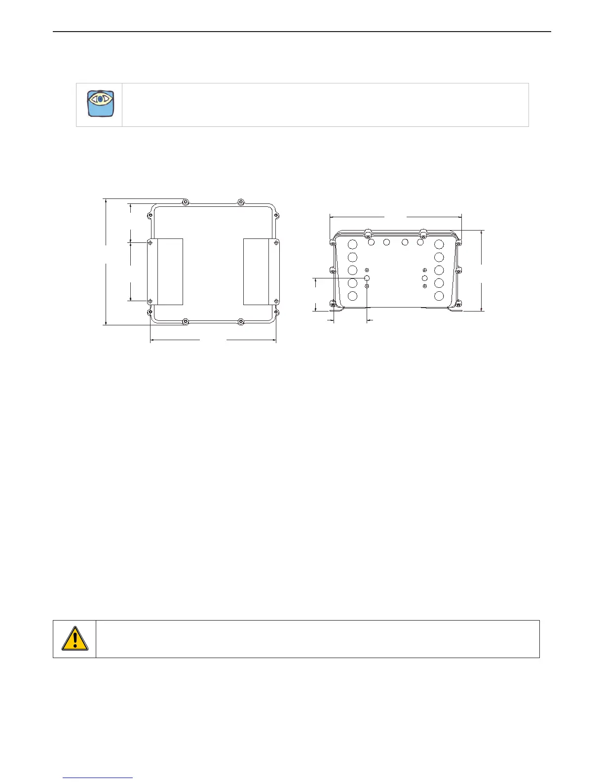
Figure 3-1: Processor Dimensions
• Bonding is required for maximum electromagnetic compatibility (EMC) performance. Refer to MMC-
287 Grounding (Bonding).
• Locate the Processor such that the push-pull cables have the shortest, most direct path to the selector
lever. The push-pull cable length should not exceed 20 feet (6,0m), the bend radius should not be less
than 10 inches (254mm) and the total degrees of bends must be less than 270 degrees.
Only when the previous items have been completed, should you start the actual installation. The following
sections describe the requirements for installing the components and selecting mounting locations.
3.1.1 Processor(s)
Processors required per engine:
• Single Screw: One (1) Processor
• Twin Screw: Two (2) Processors
Mounting Hardware is installer supplied.
Installation/Troubleshooting Manual is included with the Processor.
The following items must be taken into account when selecting the location for the Processor(s):
• The Processor is spray proof, but not water proof. Therefore, an area must be selected that
typically stays dry.
• The engine room is the preferred location for mounting the Processor.
• If the engine room is too small, locate in any area where it is easily accessible, as long as all of
the criteria listed are met.
• Bulkhead mounting is the preferred method due to ease of access for wiring and adjustments.
However, the Processor can be mounted in any attitude as long as the Display LED window
and push buttons are accessible.
NOTE: ZF Marine Propulsion Systems Miramar, LLC recommends that the system be installed in accordance
with ABYC, E-11 and P24.
4.75
(120,7mm)
3.20
(81,3mm)
10.25
(260,4mm)
10.40
(264,2mm)
6.70
(170,2mm)
2.69
(68,3mm)
10.71
(272mm)
2.70
(68,6mm)
12256-
WARNING: Note that the dimensions are out of scale, pay attention to properly size the cut out before use !

 Loading...