InteliLite 9 Global Guide
322
Related FW 1.1.0 Related applications AMF, MRS
Comm object 2
Description
The output is designed to be used as external alarm indication such as a red bulb in the control room etc. The
output is active when at least one unconfirmed alarm is present in the alarmlist and remains active until
confirmation of alarm.
Alarm
6 back to Logical binary outputs alphabetically
LBO: C
Related FW 1.1.0 Related applications AMF, MRS
Comm object 40
Description
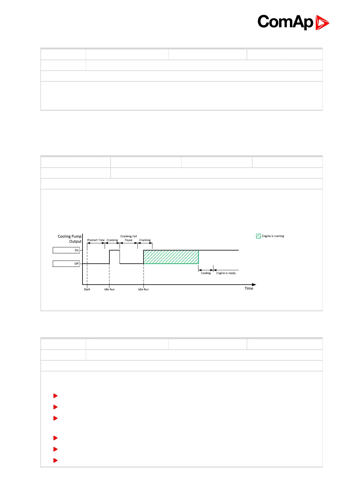
This output is dedicated for coolant pump control. It is closed in the moment the gen-set is started and
remains closed until the gen-set is stopped and After Cooling Time (page 178) elapses or the cranking pause
or the Emergency Stop occurs or the controller is switched to OFF mode.
Image 8.23 Cooling Pump
Cooling Pump
6 back to Logical binary outputs alphabetically
Related FW 1.1.0 Related applications AMF, MRS
Comm object 2091
Description
Logical binary output for choke valve control. Output CHOKE is activated every time when logical binary
output STARTER (PAGE 344) is activated. Output is deactivated when one of these conditions is fulfilled:
Choke Time is elapsed
Generator voltage is higher than Choke Voltage
Logical binary input Choke Inhibit is activated
Or when some of these situations during start occurs:
Any second level alarm
Emergency stop
Stop command
Choke

 Loading...