Home
ComAp
Controller
InteliLite 9
ComAp InteliLite 9 User Manual
5
of 1
of 1 rating
401 pages
Give review
Manual
Specs
To Next Page
To Next Page
To Previous Page
To Previous Page
Loading...
Inteli
Lite
9
Gl
obal
Gui
de
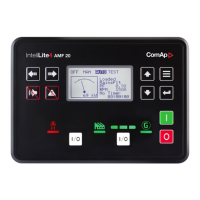
50
I
mage
5.8
Sec
on
d
s
cr
een
of
Int
el
i
Con
f
i
g
-
sel
ec
t
I
nt
er
net
/Et
hernet
C
on
n
ecti
o
n
u
sing
WinS
co
pe
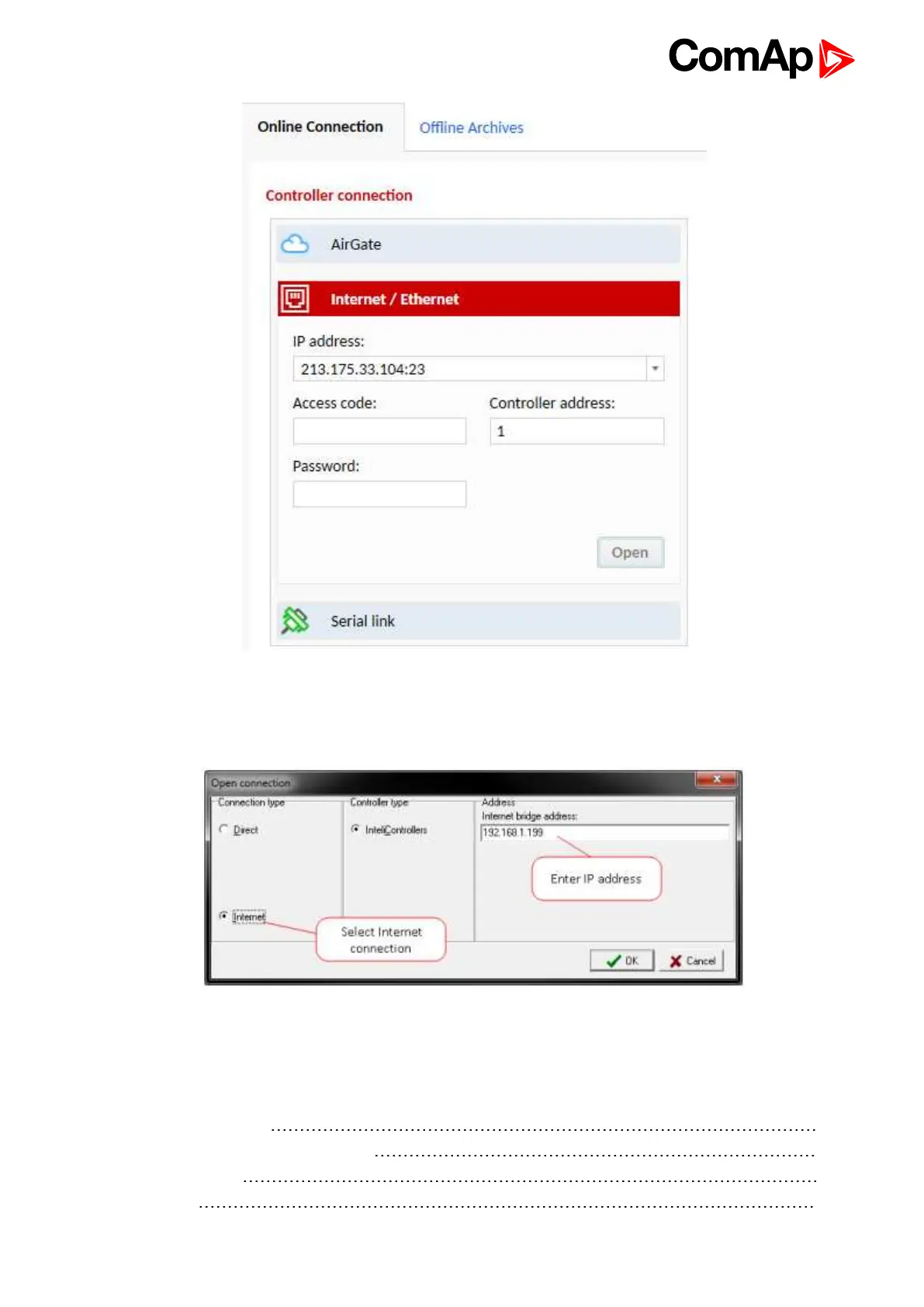
I
mage
5.9
Wi
nS
c
op
e
scree
n
5.3
O
per
a
tor
Gui
de
5
.
3.1
Fr
on
t
pa
n
el
ele
me
nts
5
1
5
.
3.2
D
is
p
lay
s
c
r
ee
ns
a
nd
p
ag
es
st
ru
ct
ur
e
5
2
5
.
3.3
Bro
ws
ing
ala
r
ms
6
5
5
.
3.4
Pass
w
o
rd
6
6
49
51
Table of Contents
Default Chapter
2
Table of Contents
2
1 Document Information
6
Clarification of Notation
6
About this Global Guide
6
Legal Notice
6
General Warnings
8
Remote Control and Programing
8
SW and HW Versions Compatibility
8
Dangerous Voltage
8
Adjust the Setpoints
8
Certifications and Standards
9
Document History
9
Symbols in this Manual
10
2 System Overview
11
General Description
11
The Key Features of Intelilite
11
True RMS Measurement
11
Configurability and Monitoring
11
Supported Configuration and Monitoring Tools
12
Configuration Parts
12
Principle of Binary Inputs and Outputs Configuration
12
PC Tools
13
Inteliconfig
13
Winscope
13
Plug-In Modules
14
CM-Ethernet
14
CM-4G-Gps
14
CM-Gprs
15
CM-Rs232-485
15
Em-Bio8-Efcp
15
3 Applications Overview
16
AMF - Automatic Mains Failure Start
16
MRS - Manual Remote Start
16
MRS Application Overview
17
4 Installation and Wiring
18
Package Content
18
Controller Installation
18
Dimensions
18
Mounting
19
Panel Door Mounting
19
Terminal Diagram
20
Recommended Wiring
21
General
22
Grounding
22
Power Supply
22
Measurement Wiring
23
Power Supply Fusing
23
CT Location
24
Current Measurement Wiring
24
3 Phase Application:
25
Split Phase Application
25
Mono Phase Application
26
Voltage Measurement AMF Wiring
26
Connectiontype: 3 Phase 4 Wires
27
Connectiontype: 3 Phase 3 Wires
27
Connectiontype: Split Phase
28
Connectiontype: Mono Phase
28
Magnetic Pick-Up
30
Binary Inputs
32
Binary Outputs
33
E-Stop
34
Analog Inputs
34
Analog Inputs with Voltage & Current Sensors
35
Voltage Sensors
35
Wiring of Analog Input with Voltage Sensor
36
Wiring of Analog Input with Current Sensor
37
Analog as Binary or Tristate Inputs
38
CAN Bus Wiring
38
CAN Bus Topology
39
CAN Bus Wiring for Shorter Distances
39
Usb
40
CAN Bus Wiring for Longer Distances
40
USB Connection
40
Example of AMF Wiring
41
Example of MRS Wiring
42
Plug-In Module Installation
43
5 Controller Setup
45
Default Configuration
45
Binary Inputs AMF
45
Binary Outputs AMF
45
Binary Outputs MRS
46
Controller Configuration and PC Tools Connection
46
Analog Inputs
46
Usb
46
Connection Using Inteliconfig
47
Connection Using Winscope
47
Rs232/Rs485
47
Ethernet
49
Direct Connection
49
Operator Guide
50
Front Panel Elements
51
Display Screens and Pages Structure
52
Main Screen
53
Measurement Screens
53
Setpoint Screens
59
Browsing Alarms
65
Password
66
Change Password
68
Log out from Controller
70
Lost Password
71
Password Break Protection
71
Information Screen
72
Language Selection
73
Display Contrast Adjustment
74
Functions
74
Start-Stop Sequence
75
AMF Sequence
77
Operating Modes
78
Off
78
Man
78
Auto
78
Engine Start
79
Test
79
Diesel Engine
79
Stabilization
81
Connecting to Load
81
MRS Operation
81
AMF Operation
81
Engine Cool down and Stop
82
Mains Failure Detection
82
Healthy Mains Detection
82
The AMF Procedure
82
Alarm Management
83
Stopped Gen-Set Evaluation
83
Alarm Handling
84
Analog Input Alarm Evaluation Principle
84
Alarm States
85
Warning (Wrn)
85
Alarm Indication Only
85
History Record Only (Histreconl)
85
Sensor Fail Detection (FLS)
86
Breaker Open and Cool down (BOC)
86
Remote Alarm Messaging
86
Alarmlist
87
Controller Built-In Alarms
87
User Configured Alarms
87
ECU Alarms
87
History Log
89
Record Structure
89
Breaker Control
90
Breaker Control Outputs
91
MCB Special Requirements
91
Breaker Fail Detection
92
Breaker Fail - Breaker Close/Open in Steady Position - Open
92
Breaker Fail - Breaker Close/Open in Steady Position - Close
92
Exercise Timer
93
Available Modes of Timer
94
Once Mode
94
Set-Up Via Inteliconfig
94
Daily Mode
95
Set-Up Via Controller Interface
95
Weekly Mode
96
Monthly Mode
96
Short Period Mode
99
Service Timers
99
Flowchart
101
Additional Running Engine Indications
102
Voltage Phase Sequence Detection
102
Gen-Set Operation States
102
Engine Started Conditions
103
Engine Running Conditions
103
Still Engine Conditions
103
Stop Engine Conditions
103
Electric State Machine
104
Sensor Curves
105
Default Sensor Curves
105
Tier 4 Final
105
Providing After-Treatment Status Information
106
After-Treatment Screen
106
Example of Active Tier 4 Final Screen
106
Example of Inactive Tier 4 Final Screen
106
Control of After-Treatment Regeneration Function
108
Analog Values
108
Alternate Configuration
108
E-Stop
109
ECU Frequency Selection
110
Visualization on CU Screen
110
Direct Communication
111
Connection Via RS232
111
Connection Via RS485
111
Connection Via Ethernet
112
Connection Via USB
112
Remote Communication
113
Ethernet LAN Connection
113
Setting-Up Static IP Address
113
Internet Connection
114
Public Static IP
114
Event SMS
114
Alarm SMS
115
SMS Commands
115
Event Email
116
Web Server
119
Scada
120
Measurement
121
Setpoints
122
History
123
Web Server Adjustment
124
Connection to 3Rd Party Systems
124
Modbus-Rtu, Modbus/Tcp
124
Address Space
125
Mapping Data Types to Registers
125
Error Codes (Exception Codes)
127
Reserved Registers
127
MODBUS Examples
130
Modbus RTU Examples
130
Reading of Battery Voltage
130
Reading Nominal Power
130
Reading All Binary Inputs as Modbus Register
131
Reading Binary Inputs as Coil Status.
132
Starting the Engine
133
Nominal Power – Writing
135
CRC Calculation
135
Modbus TCP Examples
136
7 Technical Data
137
8 Appendix
139
Controller Objects
140
List of Setpoint Groups
141
List of Setpoints
142
Gen-Set Name
145
Group: Basic Settings
145
Nominal Power Split Phase
145
Nominal Current
146
Nominal Power
146
Connection Type
147
CT Ratio
147
Generator Winding Connection System
148
Nominal Voltage Ph-N
149
Nominal Voltage Ph-Ph
149
PT Ratio
149
Nominal Frequency
150
VM PT Ratio
150
Gear Teeth
151
Nominal RPM
151
Controller Mode
152
GCB Mode
153
Controller Address
154
Operation Mode
154
Backlight Timeout
155
Reset to Manual
155
Horn Timeout
156
Zero Power Mode
156
Power on Mode
157
Runhourssource
157
Main Screen Line 1
158
Screen Filter
159
Cranking Attempts
160
Cranking Fail Pause
160
Maximum Cranking Time
160
Prestart Time
161
Starting RPM
161
Glow Plugs Time
162
Starting Oil Pressure
162
Fuel Pump off
163
Fuel Pump on
164
Choke Function
165
Choke Time
165
Choke Start Temp
166
Choke Increment
167
Choke Voltage
168
Choke Lead
169
D+ Function
169
D+ Treshold
170
D+ Alarm Type
171
D+ Delay
171
Fuel Solenoid Lead
172
Idle Time
172
Minimal Stabilization Time
174
Maximal Stabilization Time
175
Protection Hold off
175
Cooling Speed
176
Cooling Time
176
Stop Time
176
After Cooling Time
178
Overspeed Sd
178
Underspeed Sd
178
Oil Pressure Wrn
179
Overspeed Overshot
179
Overspeed Overshot Period
179
ECU Oil Pressure Wrn
180
Oil Pressure Delay
180
Oil Pressure Sd
180
Coolant Temperature Wrn
181
ECU Oil Pressure Delay
181
ECU Oil Pressure Sd
181
Coolant Temperature Delay
182
Coolant Temperature Sd
182
ECU Coolant Temperature Wrn
182
Coolant Temperature Low Wrn
183
ECU Coolant Temperature Delay
183
ECU Coolant Temperature Sd
183
Coolant Temperature Low Delay
184
Fuel Level Sd
184
Fuel Level Wrn
184
ECU Fuel Level Sd
185
ECU Fuel Level Wrn
185
Fuel Level Delay
185
ECU Fuel Level Delay
186
Transfer Wrn Delay
186
Maintenance Timer
187
Subgroup: Maintenance
187
Battery Overvoltage
188
Battery Undervoltage
188
Battery <> Voltage Delay
189
Low Battery Charging Cycle
189
ECU Speed Adjustment
191
Ventilation Pulse Time
191
Group: Generator Settings
192
Overload BOC
192
Overload Delay
192
Overload Wrn
192
Generator Overvoltage Sd
193
Short Circuit BOC
193
Short Circuit BOC Delay
193
Generator Overvoltage Wrn
194
Generator Undervoltage BOC
194
Generator Undervoltage Wrn
194
Generator <> Voltage Delay
195
Generator Overfrequency BOC
195
Generator Overfrequency Wrn
195
Generator <> Frequency Delay
196
Generator Underfrequency BOC
196
Generator Underfrequency Wrn
196
Group: Protections
197
Overload Protection
197
Short Circuit Protection
197
Generator <> Voltage Protection
198
Generator Frequency Protection
198
Overspeed Protection
199
Underspeed Protection
199
Emergency Start Delay
200
Group: AMF Settings
200
Mains Return Delay
200
Transfer Delay
201
Mains Overvoltage
202
MCB Close Delay
202
Mains < > Voltage Delay
203
Mains Overfrequency
203
Mains Undervoltage
203
Mains < > Frequency Delay
204
Mains Underfrequency
204
Return from Island
204
MCB Logic
205
Return from Test
205
Analog Protection 1 Wrn
207
MCB Opens on
207
Analog Protection 1 Delay
208
Analog Protection 1 Sd
208
Analog Protection 2 Sd
209
Analog Protection 2 Wrn
209
Analog Protection 2 Delay
210
Analog Protection 3 Wrn
210
Analog Protection 3 Delay
211
Analog Protection 3 Sd
211
Date
212
Group: Scheduler
212
Time
212
Time Stamp Period
212
Summer Time Mode
213
Timer 1 Refresh Period
218
Timer 1 Day
219
Timer 1 Weekends
219
Timer 1 Repeat Day
220
Timer 1 Repeat Day in Month
220
Timer 1 Repeated Day in Week
220
Group: CM-RS232-485
221
Group: Plug-In Modules
221
Timer 1 Repeat Week in Month
221
COM1 Communication Speed
222
COM1 MODBUS Communication Speed
222
COM2 Communication Speed
223
COM2 Mode
223
COM2 MODBUS Communication Speed
224
Group: CM-GPRS
224
Message Language
224
Event Message
225
Time Zone
225
BOC Message
226
Sd Messages
226
Wrn Message
226
Group: CM-4G-GPS
227
Required Connection Type
227
Telephone Number 1
227
Group: CM-Ethernet
231
Group: Alternate Config
239
Nominal Frequency 1
239
Nominal RPM 1
239
Nominal Voltage Ph-N 1
240
Nominal Voltage Ph-Ph 1
240
Nominal RPM 2
243
Values
258
List of Values
259
DEF Level
261
DPF Ash Load
261
DPF Soot Load
261
Group: Engine
261
Ecu-Bin 2
262
Ecu-Bin 3
262
Ecu-Bin 4
262
Ecu-Bin 5
262
Ecu-Bin 6
263
Ecu-Bin 7
263
Ecu-Bin 8
263
Ecu-Bin 9
263
ECU Frequency Select
264
ECU State
264
Ecu-Bin-Ext-1
264
Generator Frequency
265
Rpm
265
Speed Request
265
Speed Required RPM
265
Generator Voltage L1-L2
266
Generator Voltage L1-N
266
Generator Voltage L2-L3
266
Generator Voltage L2-N
266
Generator Voltage L3-N
267
Group: Load
268
Load Characteristic L1
269
Load Characteristic L2
269
Load Characteristic L3
269
Load Kva
269
Load Kva L1
270
Load Kva L2
270
Load Kva L3
270
Load Kvar
270
Load Kvar L1
271
Load Kvar L2
271
Load Kvar L3
271
Load Kw
271
Load Kw L1
272
Load Kw L2
272
Load Kw L3
272
Load Power Factor
272
Group: Mains
273
Load Power Factor L1
273
Load Power Factor L2
273
Load Power Factor L3
273
Mains Voltage L1-N
274
Mains Voltage L2-L3
274
Mains Voltage L2-N
274
Mains Voltage L3-L1
274
Group: Controler I/O
275
Engine State
280
FW Branch
280
FW Version
280
ID String
280
Group: Log Bout
281
SPI Module a
281
Timer Text
281
Log Bout 2
282
Log Bout 3
282
Log Bout 4
282
Log Bout 5
282
Cell Diag Code
284
Cell Errorrate
285
Cell Signal Lev
286
Cell Status
286
Operator
286
Last Email Result
291
MAC Address
291
Current Subnet Mask
292
Em Bio a
292
Logical Binary Inputs
293
Logical Binary Inputs Alphabetically
294
Emergency Stop
305
Fault Reset Button
305
Force Regeneration
305
Fuel Pump On/Off
306
GCB Feedback
307
Horn Reset Button
308
Mains Fail Block
308
MCB Feedback
309
Not Used
310
Protection Enable
310
Regeneration Inhibit
310
Remote AUTO
310
Remote man
311
Remote off
311
Rem TEST on Load
312
Remote Start/Stop
312
Remote TEST
313
Sd Override
313
Alphabetical Groups of Logical Binary Outputs
314
Logical Binary Outputs
314
Logical Binary Outputs Alphabetically
315
AL AIN 1 Sd+Boc
316
AL AIN 1 Wrn
316
AL AIN 2 Sd+Boc
316
AL AIN 2 Wrn
316
AL AIN 3 Wrn
317
AL Battery Flat
317
AL Battery Overvoltage
317
AL Battery Undervoltage
317
AL Common BOC
318
AL Common Fls
318
AL Common Sd
318
AL Common Wrn
318
AL Coolanttemp Low
319
AL Coolanttemp Sd
319
AL Coolanttemp Wrn
319
AL D+ Fail
319
AL Fuel Level Wrn
320
AL Mains Fail
320
AL Maintenance 1
320
AL Oil Press Sd
321
AL Oil Press Wrn
321
AL Overcurrent
321
AL Overspeed
321
Alarm
322
Choke
322
Cooling Pump
322
ECU Communic Error
323
ECU Communic OK
323
ECU Power Relay
324
ECU Red Lamp
324
ECU Run Stop
325
ECU Yellow Lamp
325
Exercise Timer 1
325
Fault Reset
325
Fuel Solenoid
326
Fuel Pump
327
GCB Close/Open
327
GCB Open Command
328
Repeated GCB Close Command
328
GCB off Coil
329
GCB on Coil
330
GCB on Coil Close Command
330
GCB UV Coil
330
Repeated GCB on Coil Close Command
330
GCB UV Coil Close Command
331
GCB UV Coil Open Command
331
Generator Healthy
332
Glow Plugs
332
Glow Plugs in Cranking Fail Pause
333
HEST Lamp
334
Horn
334
Idle/Nominal
335
Mains Healthy
335
MCB Close Command
336
MCB Open Command
336
Repeated MCB Close Command
336
MCB off Coil
337
MCB off Coil Command
337
MCB on Coil
338
MCB on Coil Close Command
338
Repeated MCB on Coil Close Command
338
MCB UV Coil
339
MCB UV Coil Close Command
339
Mcb UV Coil Open Command
339
Mode AUTO
340
Mode man
340
Mode off
340
Mode TEST
340
Prestart in Cranking Fail Pause
342
Ready
343
Ready to AMF
343
Ready to Load
343
Regenerationneeded
344
Starter
344
Stop Pulse
345
Stop Solenoid
345
Ventilation
346
Ventilation on Pulse
346
Ventilation off Pulse
347
Alphabetical Groups of Logical Analog Inputs
348
Logical Analog Inputs
348
Logical Analog Inputs Alphabetically
349
AIN Prot01
350
AIN Prot02
351
AIN Prot03
352
Coolant Temp
353
Lai: C
353
Fuel Level
354
Oil Pressure
355
Alarms
356
List of Alarms Level
357
Alarm Email 1 Fail
358
Alarm SMS 1 Fail
358
ECU Wait to Start
358
Warnings
358
Event SMS 1 Fail
359
Wrn Battery < Voltage
359
Wrn Battery > Voltage
359
Wrn Charging Alternator Fail
359
Wrn Coolant Temp
360
Wrn Coolant Temperature Low
360
Wrn ECU Communication Fail
360
Wrn Fuel Level
360
Wrn bin Protection
361
Wrn Generator L1 < Voltage
361
Wrn Generator L1 > Voltage
361
Wrn Generator L1L2 > Voltage
361
Wrn Generator L1L2 < Voltage
362
Wrn Generator L2 < Voltage
362
Wrn Generator L2 > Voltage
362
Wrn Oil Pressure
367
Wrn Overload
367
After-Treatment
368
Wrn Override All Sd
368
Wrn Stop Fail
368
EM(A) - a Message Lost
369
EM(A) - Configuration Mistake
369
EM(A) - Insufficient
369
EM(A) - Missing or Damaged
369
Mains CCW Rotation
370
Manual Restore
370
Module(Slota) - Comm. Outage
370
Module(Slota) - False Module
371
Module(Slota) - Unexpected
371
Module(Slota) - Unknown Module
371
Wrn Fuel Transfer Failed
371
Alarms Level 2
372
Sd Battery Flat
374
Sd Coolant Temp
374
Sd ECU Communication Fail
374
Shutdown
374
Sd AIN Protec
375
Sd bin Protection
375
Sd Fuel Level
375
Sd GCB Fail
375
Sd Generator L1 < Voltage
376
Sd Generator L1 > Voltage
376
Sd Generator L1L2 > Voltage
376
Sd Generator L2L3 < Voltage
378
Sd Generator L3 < Voltage
378
Sd Generator L3 > Voltage
378
Sd Oil Pressure
380
Sd Overload
380
Sd Overspeed
380
Sd RPM Measurement Fail
381
Sd Short Circuit
381
Sd Start Fail
381
Sd Underspeed
381
BOC AIN Prot
382
BOC Coolant Temp
382
BOC Fuel Level
382
Other Type
382
BOC Generator L1 < Voltage
383
BOC Generator L1L2 < Voltage
383
BOC Generator L2 < Voltage
383
BOC Generator L2L3 < Voltage
383
Fail Sensor and Other Types
385
Fail Sensor
388
Fls AIN Prot
388
Fls Coolant Temp
388
Fls Fuel Level
388
Modules
388
Communication Modules
389
Plug-In Modules
389
CM-Ethernet
391
Firmware Upgrade
391
Module Setup
392
How to Start Using CM-GPRS Module
393
SIM Card Settings
393
GSM Diag Code – Common List of Diagnostic Codes for Cellular Modules
394
How to Start Using CM-4G-GPS Module
396
Extension Modules
398
EM-BIO8-EFCP Wiring
400
5
Based on 1 rating
Ask a question
Give review
Questions and Answers:
Need help?
Do you have a question about the ComAp InteliLite 9 and is the answer not in the manual?
Ask a question
ComAp InteliLite 9 Specifications
General
Brand
ComAp
Model
InteliLite 9
Category
Controller
Language
English
Related product manuals
ComAp InteliLite MRS16
632 pages
ComAp InteliLite MRS11
65 pages
ComAp InteliLite MRS15
65 pages
ComAp InteliLite AMF25
735 pages
ComAp intelilite nt amf20
145 pages
ComAp InteliLite 4 AMF 20
620 pages
ComAp intelilite nt amf25
145 pages
ComAp InteliLite NT AMF 25
9 pages
ComAp InteliLite NT AMF Series
84 pages
ComAp InteliLite4 AMF20
31 pages
ComAp InteliLite4 AMF25
31 pages
ComAp InteliSys NT
44 pages