3-8
3-1 Servo Drive Specifications
3
Specifications
R88D-GT75H
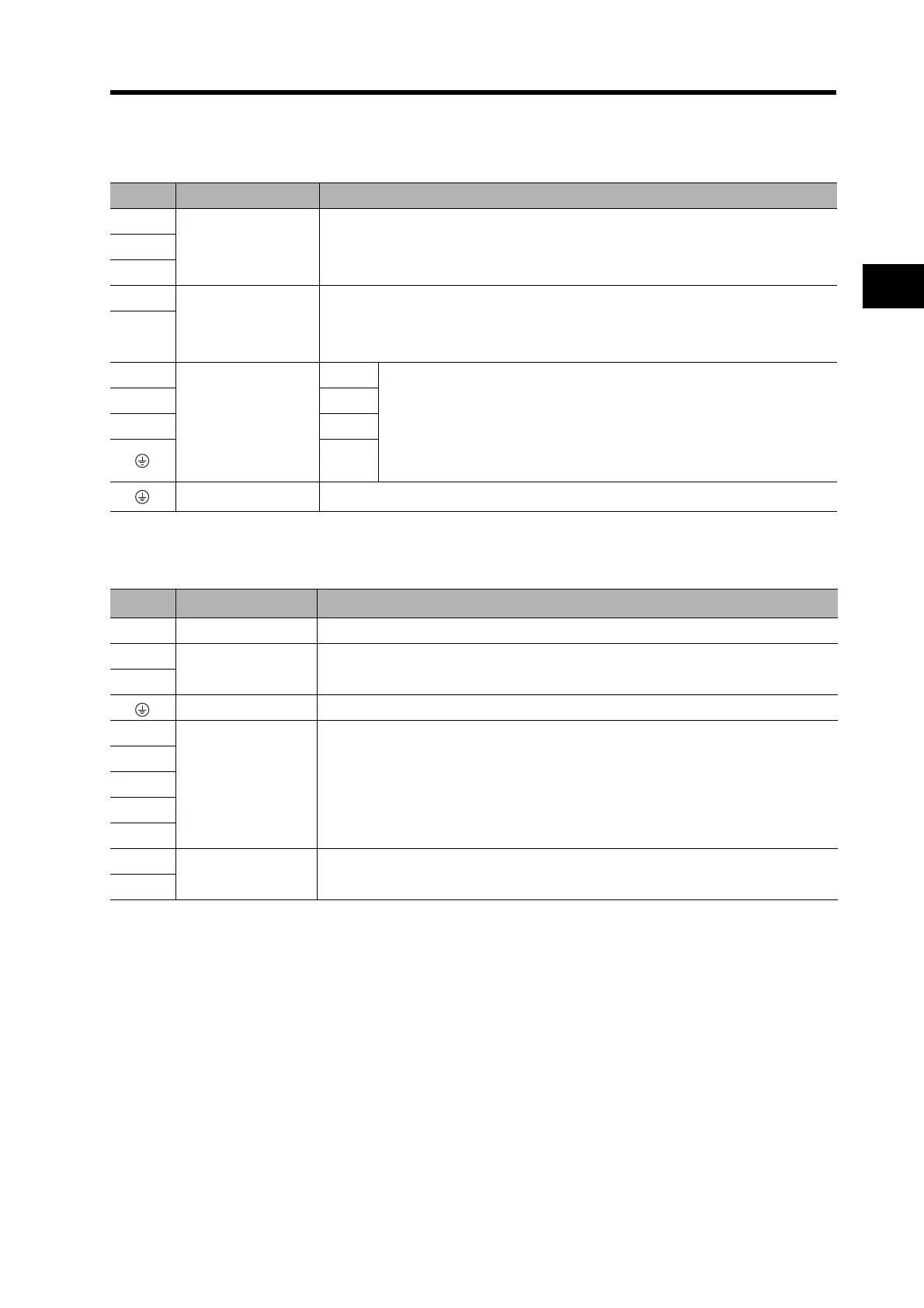
Main Circuit Terminal Block Specifications (TB1)
Main Circuit Terminal Block Specifications (TB2)
Symbol Name Function
L1
Main circuit power
supply input
R88D-GT75H (6 to 7.5 kW): Three-phase 200 to 230 VAC (170 to 253 V),
50/60Hz
L2
L3
B1 External
Regeneration
Resistor connection
terminals
6 kW, 7.5 kW: A regeneration resistor is not built in.
Connect an External Regeneration Resistor between B1 and B2,
if necessary.
B2
U
Servomotor
connection terminals
Red
These are the output terminals to the Servomotor.
Be sure to wire them correctly.
VWhite
WBlue
Green/
Yellow
Frame ground This is the ground terminal. Ground to 100 Ω or less.
Symbol Name Function
NC --- Do not connect.
L1C
Control circuit
power supply input
R88D-GT75H: Single-phase 200 to 230 VAC (170 to 253 V), 50/60Hz
L2C
Frame ground This is the ground terminal. Ground to 100 Ω or less.
NC
--- Do not connect.
EX1
EX2
EX3
NC
FN(+)
Fan Stop Output
Outputs a warning signal when the fan inside the Servo Drive stops.
(30 VDC, 50 mA max.)
FN(−)

 Loading...

