9-5
9-1 Connection Examples
9
Appendix
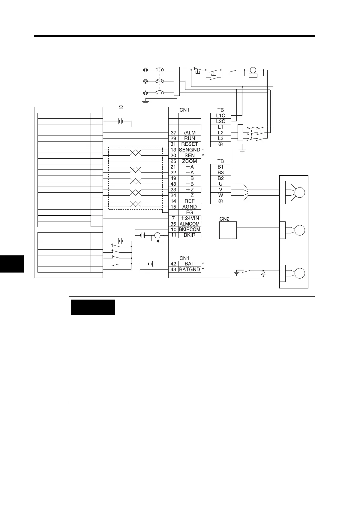
Connection Example 5: Connecting to a SYSMAC Motion Control Unit
• The example shows a three-phase, 200-VAC input to the Servo Drive for
the main circuit power supply. Be sure to provide a power supply and
wiring conforming to the power supply specifications for the Servo Drive in
use.
• Incorrect signal wiring can cause damage to Units and the Servo Drive.
• Leave unused signal lines open and do not wire them.
• Connect terminals and wiring marked with an asterisk (*) when using an
Absolute Encoder.
• This wiring diagram is an example of X-axis wiring only. For other axes,
connections must be made in the same way with the Servo Drive.
• Always close unused NC input terminals at the Motion Control Unit’s I/O
connectors.
• Make the setting so that the Servo can be turned ON and OFF with the
RUN signal.
No.
1
2
3
4
5
8
9
10
11
12
13
14
15
16
17
18
20
19
1
10
4
2
6
14
No.
XB
M
E
B
XB
R
S
T
MC1
NFB
MC2
Reactor
Servomotor Power
Cable
R88A-CAG@
CS1W-MC221/421 (-V1)
R88D-GT@
R88M-G@
Contents
Contents
I/O connector
Red
White
Blue
Green/
Yellow
Noise filter
3-phase 200 to 240 VAC 50/60 Hz
(Ground to
100
or less.)
Encoder Cable
R88A-CRG@
Brake Cable
R88A-CAGA@B
R88A-CAGE@B
24 VDC
24 VDC
Battery*
2.8 to 4.5 V DC
24 VDC
24 VDC
Shell
24 V input
24 V input ground
X-axis alarm input
X-axis RUN command output
X-axis alarm reset output
X-axis SEN signal ground
X-axis SEN signal output
X-axis feedback ground
X-axis phase A input
X-axis phase A input
X-axis phase B input
X-axis phase B input
X-axis phase Z input
X-axis phase Z input
X-axis speed command
X-axis speed command ground
24 V output
24 V output ground
24 V input
X-axis CW limit input
X-axis CCW limit input
X-axis emerg. stop input
X-axis origin proximity input
24 V input ground
DRV connector
ONOFF
X
1MC
Main circuit power supply
Main-circuit contactor
1MC
Surge
suppressor
Precautions
for Correct Use

 Loading...

