9-2
9-1 Connection Examples
9
Appendix
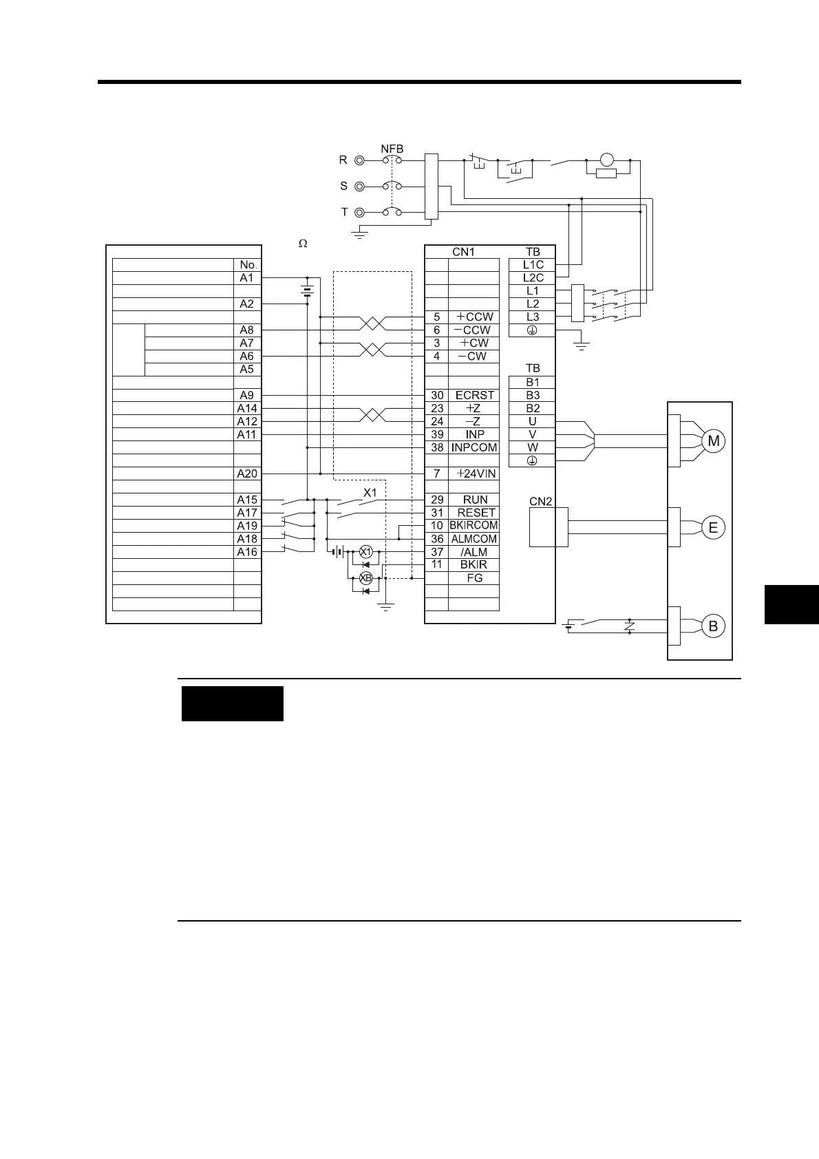
Connection Example 2: Connecting to SYSMAC CJ1W-NC113/213/413
• The wiring for the pins with * is the same as it is when a Servo Relay Unit
Cable is used. Set Pn40 (Command Pulse Input Selection) to 0
(photocoupler input).
• The example shows a three-phase, 200-VAC input to the Servo Drive for
the main circuit power supply. Be sure to provide a power supply and
wiring conforming to the power supply specifications for the Servo Drive in
use.
• Incorrect signal wiring can cause damage to Units and the Servo Drive.
• Leave unused signal lines open and do not wire them.
• Use mode 2 for origin search.
• The diode recommended for surge absorption is the RU 2 manufactured
by Sanken Electric or the equivalent.
• Make the setting so that the Servo can be turned ON and OFF with the
RUN signal.
MC1 MC2
*
*
*
*
ONOFF
X
1MC
Main circuit power supply
Main-circuit contactor
0-V power supply for output
24-V power supply for outputs
Reactor
Servomotor Power
Cable
R88A-CAG@
CJ1W-NC113/213/413
R88D-GT@
R88M-G@
Contents
X-axis dev. cntr. reset output
X-axis origin line driver input
X-axis origin common
X-axis positioning complete input
Input common
X-axis external interrupt input
X-axis origin proximity input
X-axis CCW limit input
X-axis CW limit input
X-axis emerg. stop input
X-axis
pulse
output
Red
White
Blue
Green/
Yellow
Noise filter
3-phase 200 to 240 VAC 50/60 Hz
(Ground to
100
or less.)
Encoder Cable
R88A-CRG@
Brake Cable
R88A-CAGA@B
R88A-CAGE@B
24 VDC
24 VDC
Shell
CCW (with a resistor)
CCW (without a resistor)
CW (with a resistor)
CW (without a resistor)
24 VDC
XB
1MC
Surge
suppressor
Precautions
for Correct Use

 Loading...

