3-28
3-1 Servo Drive Specifications
3
Specifications
Encoder Outputs (Phases A, B, and Z)
Pin 21: +A, 22: −A, 48: −B, 49: +B, 23: +Z, 24: −Z
Functions
• Pin 21 outputs the phase-A, phase-B, and phase-Z encoder signals for the Servomotor.
• The encoder outputs conform to the RS-422 communication method.
• The dividing ratio is set in the Encoder Divider Numerator Setting (Pn44) and the Encoder Divider
Denominator Setting (Pn45).
• The logical relation of phase B to the phase-A pulse is set in the Encoder Output Direction Switch
(Pn46).
• The ground for the output circuit line driver is connected to the signal ground (GND). It is not
isolated.
• The maximum output frequency is 4 Mpps (after multiplying by 4). The output frequency equals
the Servomotor encoder resolution
× (Pn44/Pn45) × 4 × Servomotor rotation speed (r/min) ÷ 60
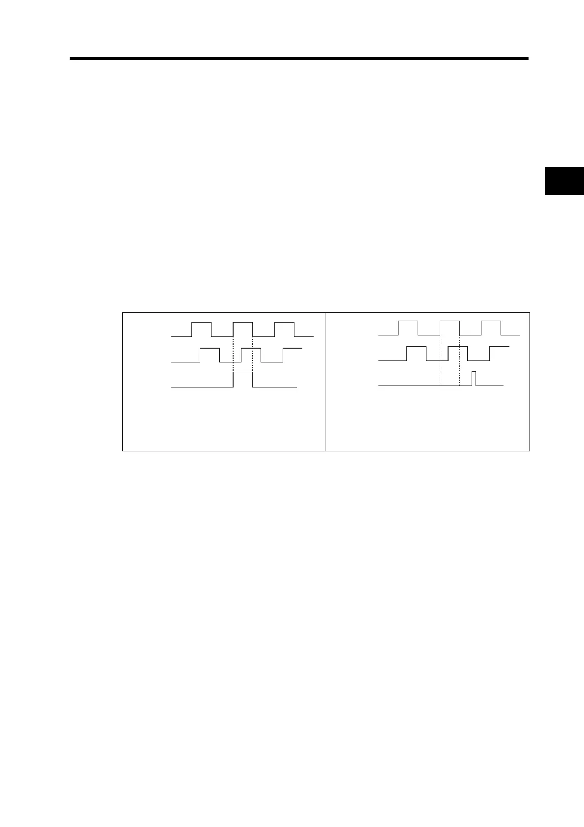
• The output phases are shown below. (They are the same for both incremental and absolute
encoders.)
• If the Servomotor encoder resolution
× (Pn44/
Pn45) is a multiple of 4, phases Z and A are
synchronized.
• In cases except for the one on the left, phases
A and Z are not synchronized.
Phase A
Phase B
Phase Z
S
nched
Not s
nched
Phase A
Phase B
Phase Z

 Loading...

