3-20
3-1 Servo Drive Specifications
3
Specifications
Control Input Details
Details on the input pins for the CN1 connector are described here.
High-speed Photocoupler Inputs:
Reverse Pulse/Forward Pulse Inputs, Feed Pulse/Direction Signal Inputs, or 90°
Phase Difference Signal Input
Pin 3: +Reverse Pulse Input (+CW), +Feed Pulse Input (+PULS), or +Phase A Input (+FA)
Pin 4: −Reverse Pulse Input (−CW), −Feed Pulse Input (−PULS), or −Phase A Input (−FA)
Pin 5: +Forward Pulse Input (+CCW), +Direction Signal (+SIGN), or +Phase B Input (+FB)
Pin 6: −Forward Pulse Input (−CCW), −Direction Signal (−SIGN), or −Phase B Input (−FB)
Functions
• The functions of these signals depend on the settings of the Command Pulse Rotation Direction
Switch (Pn41) and the Command Pulse Mode (Pn42).
• If the Command Pulse Rotation Direction Switch (Pn41) is set to 1, the rotation direction will be
reversed.
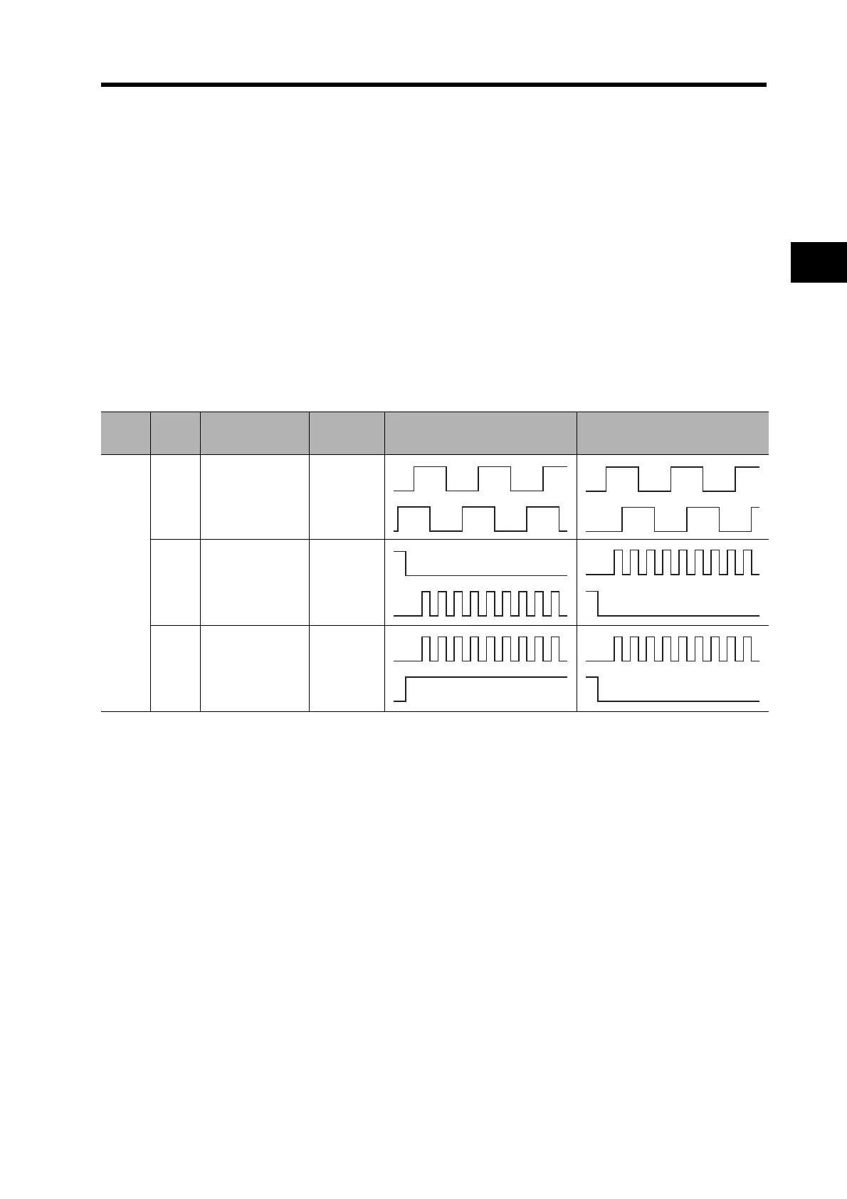
• If the photocoupler LED is turned ON, each signal will go high as shown above.
Pn41
setting
Pn42
setting
Command pulse
mode
Input pins Servomotor forward command Servomotor reverse command
0
0/2
90° phase
difference
signals
(multiplier: 4)
3: +FA
4: −FA
5: +FB
6: −FB
1
Reverse pulses/
forward pulses
3: +CW
4: −CW
5: +CCW
6: −CCW
3
Feed pulses/
direction signal
3: +PULS
4: −PULS
5: +SIGN
6: −SIGN
L
L
H L

 Loading...

