3-22
3-1 Servo Drive Specifications
3
Specifications
Line-receiver Inputs:
Reverse Pulse/Forward Pulse Inputs, Feed Pulse/Direction Signal Inputs, or 90°
Phase Difference Signal Inputs
Pin 44: +Reverse Pulse Input (+CW), +Feed Pulse Input (+PULS), or +Phase A Input (+FA)
Pin 45: −Reverse Pulse Input (−CW), −Feed Pulse Input (−PULS), or −Phase A Input (−FA)
Pin 46: +Forward Pulse Input (+CCW), +Direction Signal (+SIGN), or +Phase B Input (+FB)
Pin 47: −Forward Pulse Input (−CCW), −Direction Signal (−SIGN), or −Phase B Input (−FB)
Functions
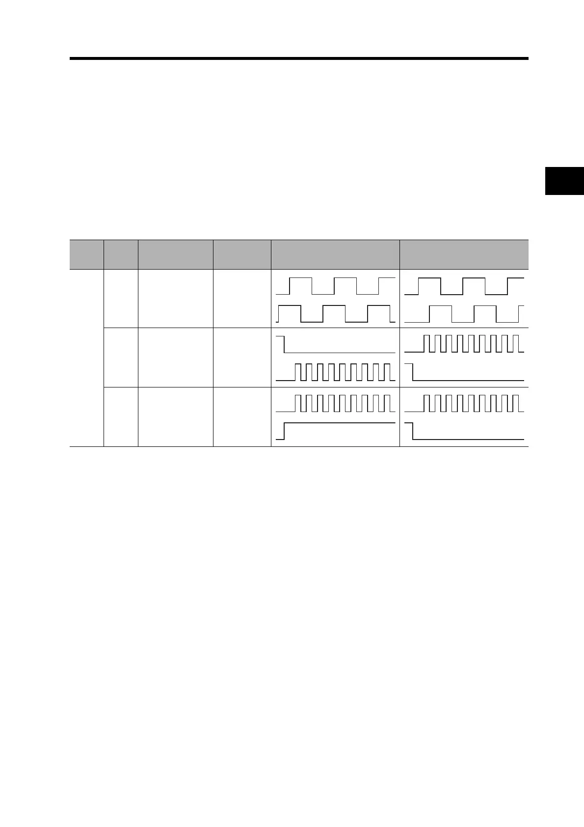
• The functions of these signals depend on the settings of the Command Pulse Rotation Direction
Switch (Pn41) and the Command Pulse Mode (Pn42).
• If the Command Pulse Rotation Direction Switch (Pn41) is set to 1, the rotation direction will be
reversed.
Pn41
setting
Pn42
setting
Command pulse
mode
Input pins Servomotor forward command Servomotor reverse command
0
0/2
90° phase
difference
signals
(multiplier: 4)
44: +FA
45: −FA
46: +FB
47: −FB
1
Reverse pulse/
forward pulses
44: +CW
45: −CW
46: +CCW
47: −CCW
3
Feed pulses/
direction signal
44: +PULS
45: −PULS
46: +SIGN
47: −SIGN
L
H L

 Loading...

