1-5
1-4 System Block Diagrams
1
Features and System Configuration
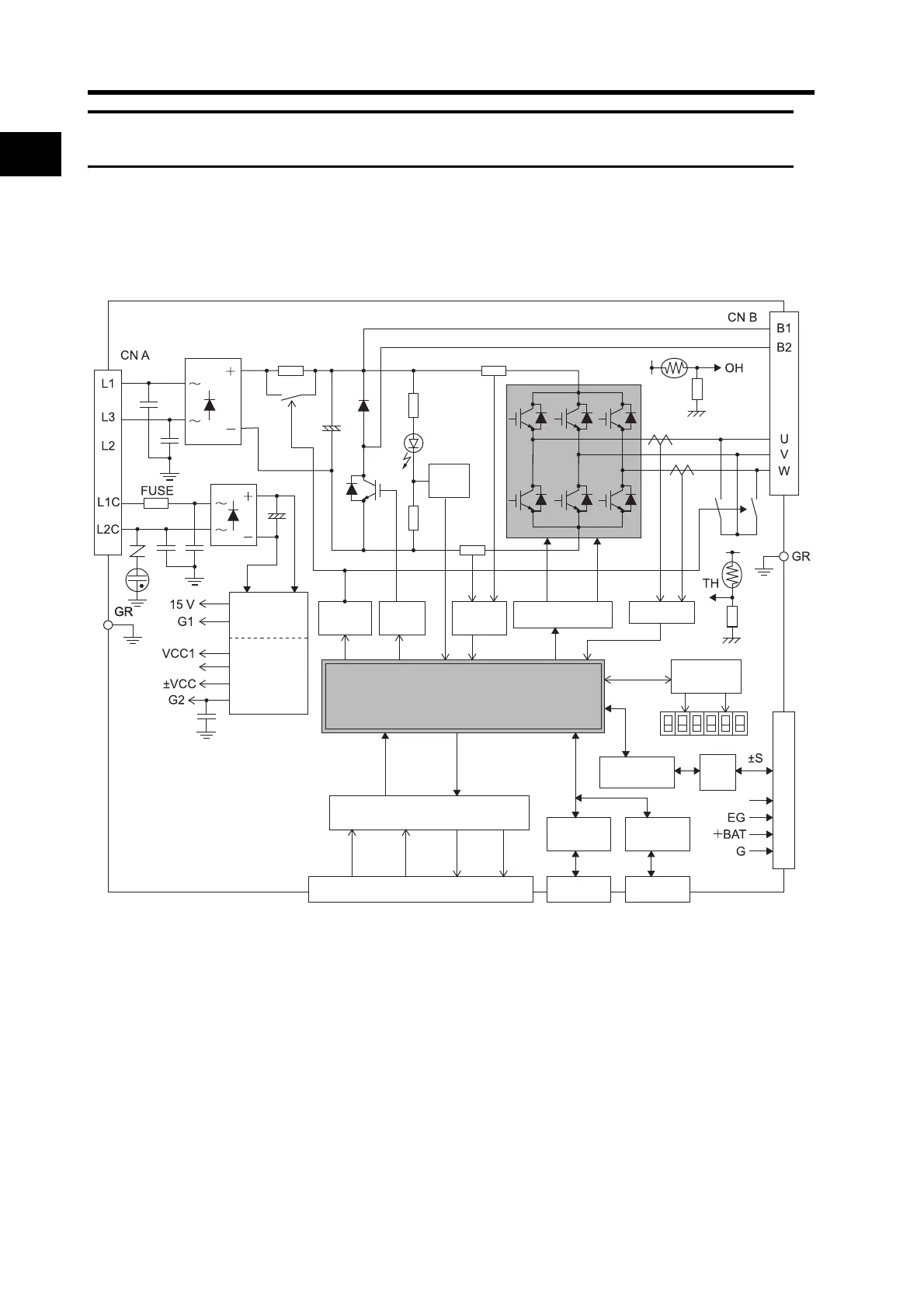
1-4 System Block Diagrams
R88D-GTA5L/-GT01L/-GT02L/-GTA5H/-GT01H/-GT02H/-GT04H
+E5V
Internal
control
power
supply
CN3A
connector
CN3B
connector
MPU & ASIC
Position, speed, and torque processor,
PWM control
Control I/O interface
Encoder
communications
interface
Display/
setting circuits
E5V
Over-
current
detection
Regene-
rative
control
CN2 encoder signal connector
SW power
supply
Main circuit
control
Relay
drive
Gate drive
Current
detection
CN1 control I/O connector
Voltage
detec-
tion
RS-232
interface
RS-485
interface
RS-
485

 Loading...

