5-59
5-16 User Parameters
5
Operating Functions
Gain Parameters (Pn10 to Pn3D)
• Use this parameter to adjust the position loop response to suit the mechanical rigidity.
• The responsiveness of the servo system is determined by the position loop gain. Servo systems
with a high loop gain have a high responsiveness and fast positioning. To increase the position
loop gain, you must improve mechanical rigidity and increase the specific oscillation frequency.
This should be 50 to 70 (1/s) for ordinary machine tools, 30 to 50 (1/s) for general-use and
assembly machines, and 10 to 30 (1/s) for industrial robots. The default position loop gain is 40
(1/s), so be sure to lower the setting for machines with low rigidity.
• Increasing the position loop gain in systems with low mechanical rigidity or systems with low
specific oscillation frequencies may cause machine resonance, resulting in an overload alarm.
• If the position loop gain is low, you can shorten the positioning time using feed forward.
• This parameter is automatically changed by executing realtime autotuning. To set it manually,
set the Realtime Autotuning Mode Selection (Pn21) to 0.
Position loop gain is generally expressed as follows:
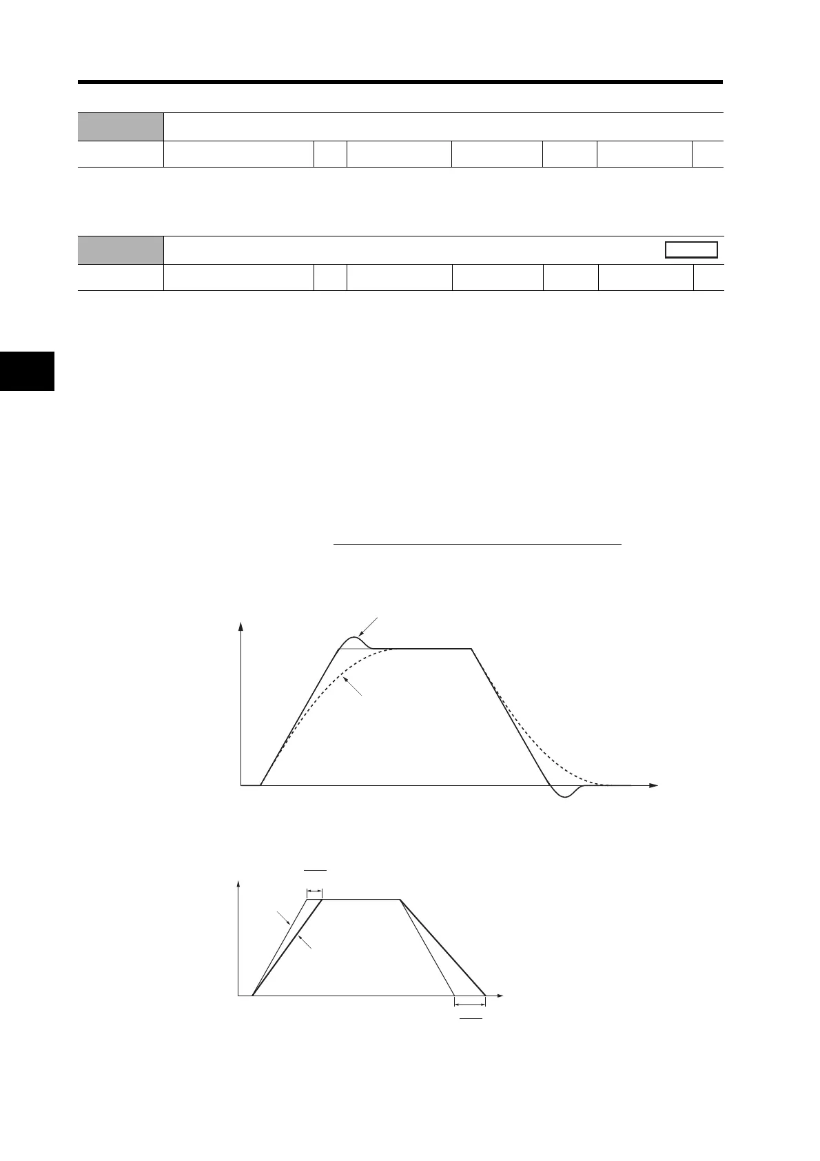
When the position loop gain is changed, the response is as shown in the following diagram.
• If the speed loop gain and position loop gain are optimally set, the Servomotor operation for the
command will be delayed 2/Kp at acceleration and delayed 3/Kp at deceleration.
Pn0F
Reserved
Setting range --- Unit --- Default setting ---
Power OFF→ON
---
Pn10
Position Loop Gain
Setting range 0 to 3000 Unit 1/s Default setting 40
Power OFF→ON
---
Position loop gain (Kp) =
Command pulse frequency (pulses/s)
Deviation counter accumulated pulses (pulses)
(1/s)
Servomotor
speed
When position loop gain is high.
When speed loop gain is low.
Time
K
3
Kp
2
Servomotor
speed
Position
command
Servomotor operation
Time

 Loading...

