1-4
1-3 Names of Parts and Functions
1
Features and System Configuration
Servo Drive Functions
Display Area
A 6-digit 7-segment LED display shows the Servo Drive status, alarm codes, parameters, and other
information.
Check Pins (IM, SP, and G)
The actual Servomotor speed, command speed, torque, and number of accumulated pulses can be
measured based on the analog voltage level by using an oscilloscope. The type of signal to output
and the output voltage level are set in the SP Selection (Pn07) and IM Selection (Pn08) parameters.
For details, refer to 5-16 User Parameters on page 5-31.
Unit No. Switch
The Servo Drive number in serial communications is set to a value from 0 to F. This number is used
to identify which Servo Drive the computer is accessing in RS-232/485 communications between
multiple Servo Drives and a computer.
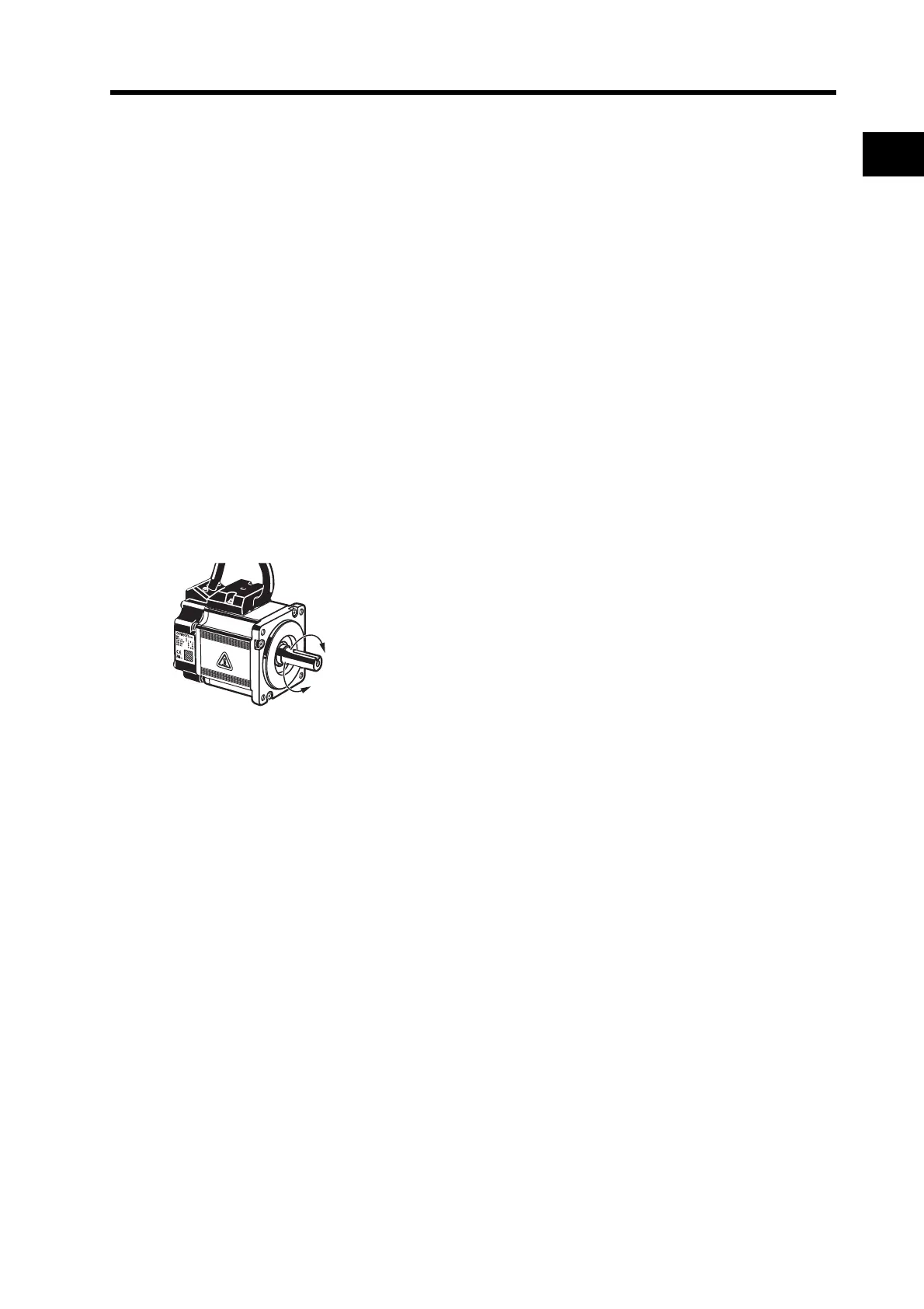
Forward and Reverse Motor Rotation
When the motor output shaft is viewed from the end,
counterclockwise (CCW) rotation is forward and clockwise
(CW) rotation is reverse.
Forward (CCW)
Reverse (CW)

 Loading...

