4. Operation
4.5 Your first EDP program
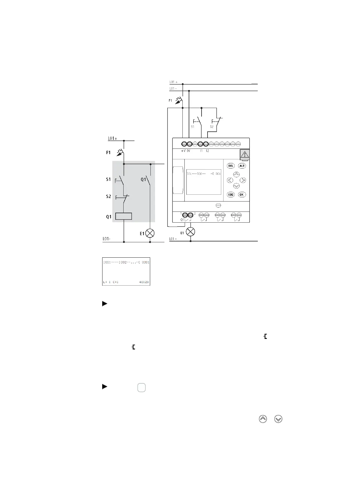
Figure 56: Lighting control circuit
Figure 57: Circuit diagram with inputs I01, I02 and output Q1
Now wire the circuit diagram as described below.
With this example the switches S1 and S2 are at the input. I001 and I002 are the
switch contacts for the input terminals in the circuit diagram .
The relay Q1 is represented in the circuit diagram by the relay coil Q001.
The symbol identifies the coil's function, in this case a relay coil acting as a contactor.
Q001 is one of the easyE4device's outputs.
From the first contact to the output coil
With easyE4 devices wire from the input to the output. The first input contact is I001.
Press the OK button.
easyE4 will insert the first contact, I001, at the cursor position.
The I flashes and can be changed,
for example, to a P for a button input by using the cursor buttons or . However,
nothing needs to be changed at this point.
easyE4 11/18 MN050009 EN www.eaton.com
107
 Loading...