5. Programming on the device
5.3 Circuit diagram elements
5.3.5 Markers and analog operands
The term "marker" is used to represent marker bits (M). Marker bits (M) are used to
store the Boolean states 0 or 1. A marker bit is also called an auxiliary relay.
easyE4 devices also manage the marker bits in marker bytes (MB), marker words
(MW) and in marker double words (MD). A marker byte consists of 8 marker bits, a
marker word of 16 marker bits and a marker double word of 32 marker bits.
You can use a specific bit and, accordingly, a specific byte to save a contact's state. For
example, marker bit 9 is also found in market byte 2, marker word 1, and marker double
word 1. You can use the following conversion table to figure out which word contains a
bit or which bits encompass a specific double word.
Bear in mind that after the division, a rounding up to the next higher integer is neces-
sary, even if the decimal number is below 0.5.
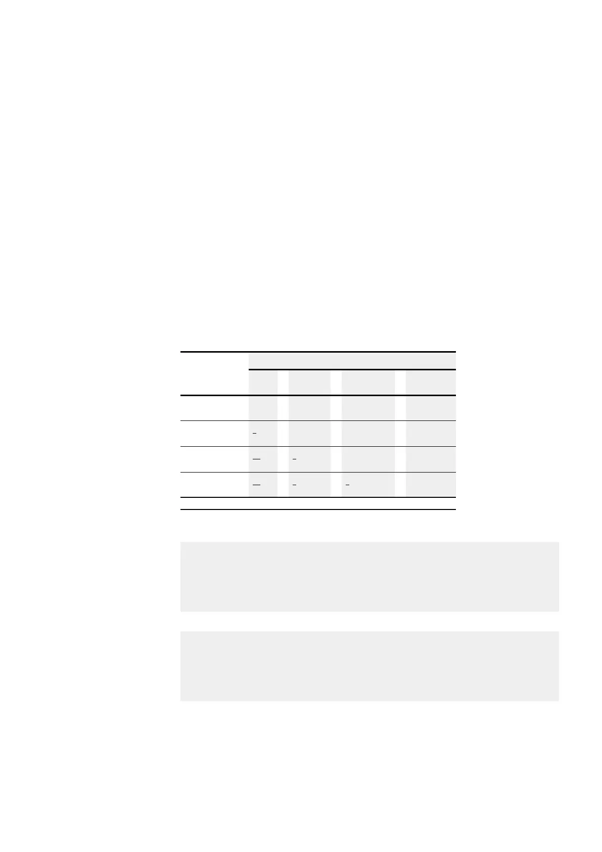
Searched for
Given
Bit
M n
Byte
MB n
Word
MW n
Double Word
DW n
Bit (M) 8n-7 to 8n 16n-15 to 16n 32n-31
up to 32n
Byte (MB) n
8
2n-1
to 2n
4n-3
to 4n
Word (MW) n
16
n
2
2n-1
to 2n
Double word (DW) n
32
n
4
n
2
n = 1 to 96
Table 56: Conversion table M, MB, MW, DW
Example 1: given Bit81 =M81; n=81;
l Byte(MB) = n/8 = 10.125 ≈11
l Word(MW) = n/16 = 5.0625 ≈6
l Double word(DW) = n/32=2.5313 ≈3
Bit81 is contained in MB11, MW6 and DW3.
Example 2: given Byte21=MB21; n=21;
l Bit(M) = 8n-7 to 8n = Bit161 to 168
l Word(MW) = n/2 = 10.5 ≈11
l Double word(DW) = n/4 = 5.25 ≈6
Byte21 contains the bits Bit161 to Bit168. Byte21 is contained in MW11 and DW6.
Marker bit (M), marker bytes (MB), marker words (MW) and marker double words
(MD) are used in the circuit and function block diagram.
Avoid any accidental double assignment of markers. In this way, you can assign the
available 96 or 128 marker bit contacts and also change the state of these marker bits
easyE4 11/18 MN050009 EN www.eaton.com
131