3. Commissioning
3.3 Switch on
3.3 Switch on
Before switching the device on, check the power supplies, inputs, outputs, and any
expansion devices and Ethernet connections to make sure that they are properly con-
nected.
3.3.1 Startup behavior of easyE4 control relays with LED indicators
If there is no program, the control relay will start in STOP mode.
These devices without a display and controls feature 2 LEDs that indicate the state of
the Ethernet port and the device status.
If there is an executable program on the easyE4 control relays, the device will start in
RUN mode.
In addition to having a valid program on the control relay,
please make sure that there are no peripheral faults that will
lead to STOP mode.
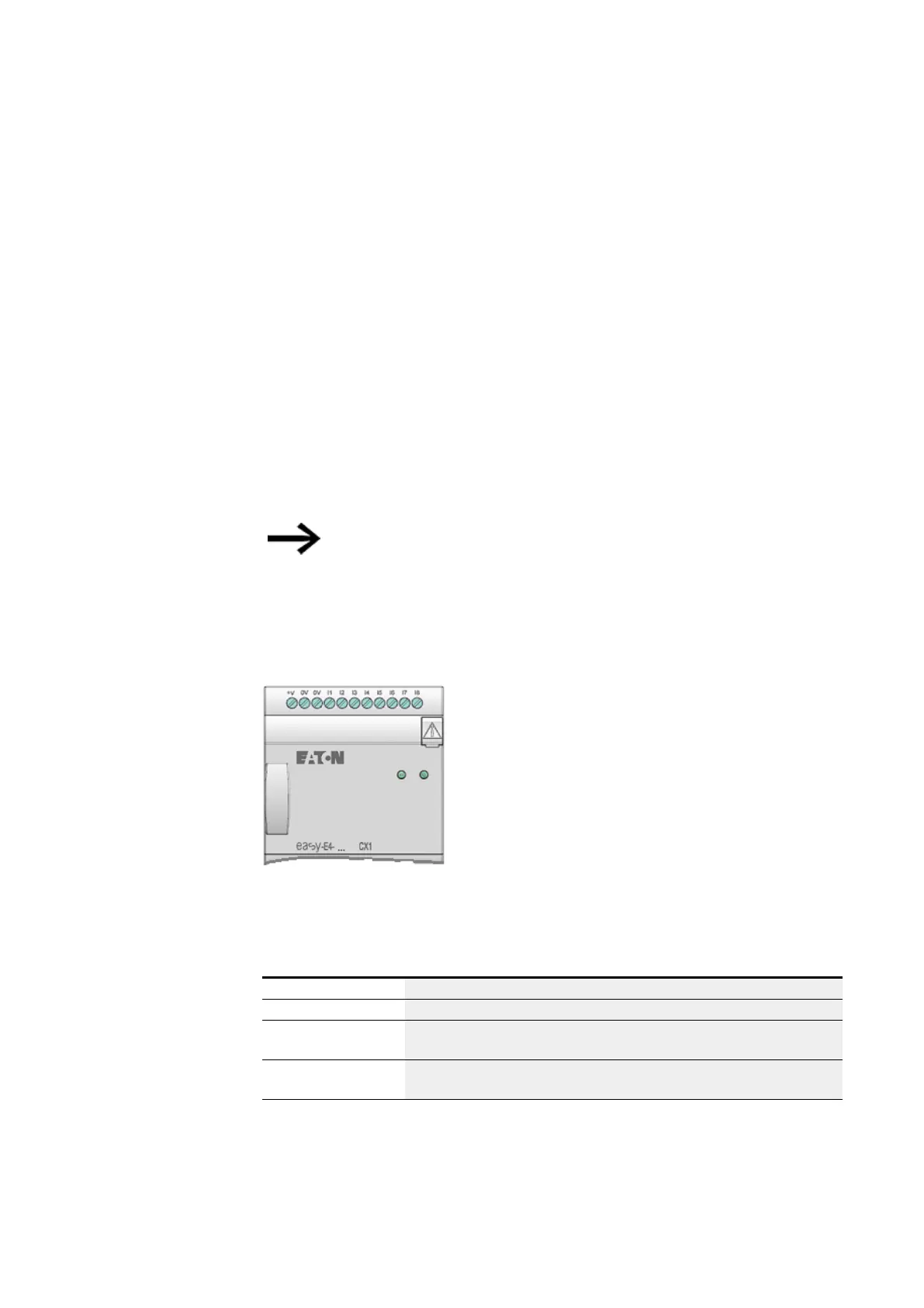
Device models without a display feature LED indicators in the front:
l 1. POW/RUN
l 2. ETHERNET (base devices only)
Figure 45: LED indicators on EASY-E4-...-12...CX1
LED POW/RUN base device
The POW/RUN LED indicates the state of the POW power supply as well as the STOP
or RUN state.
Off Malfunction or no supply voltage
Green, continuous light Supply voltage OK, RUN mode
Green,
Flashing, 1 Hz
Supply voltage OK, STOP mode
Green,
Flashing, 4 Hz
Fault at one of the expansions,
between the easyE4 device and the EASY-E4-CONNECT1 connector
76
easyE4 11/18 MN050009 EN www.eaton.com
 Loading...