6. Function blocks
6.1 Manufacturer function blocks
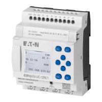
Signal diagram normal operation
Figure 153: Signal diagram for PO pulse output - possible normal mode phases
EN: Enable coil
S: Start coil for pulse sequence
FO: Operating frequency,
FS = start frequency,
m1 = Acceleration phase, m2 = Operating phase, m3 = Braking phase
AC: Pulse sequence applied at device output, contact
BR: Stop coil for pulse sequence
Q1/2: Pulse sequence at the device output Q1 and/or Q2
• Range A: The pulse sequence is present at the device output until the number of pulses defined at I1
has been reached.
• Range B: Activating the coil PO..BR initiates the braking phase and reduces the frequency of the pulse
sequence.
• Range C: A voltage drop at coil PO..EN immediately switches off the pulse sequence from the device
output.
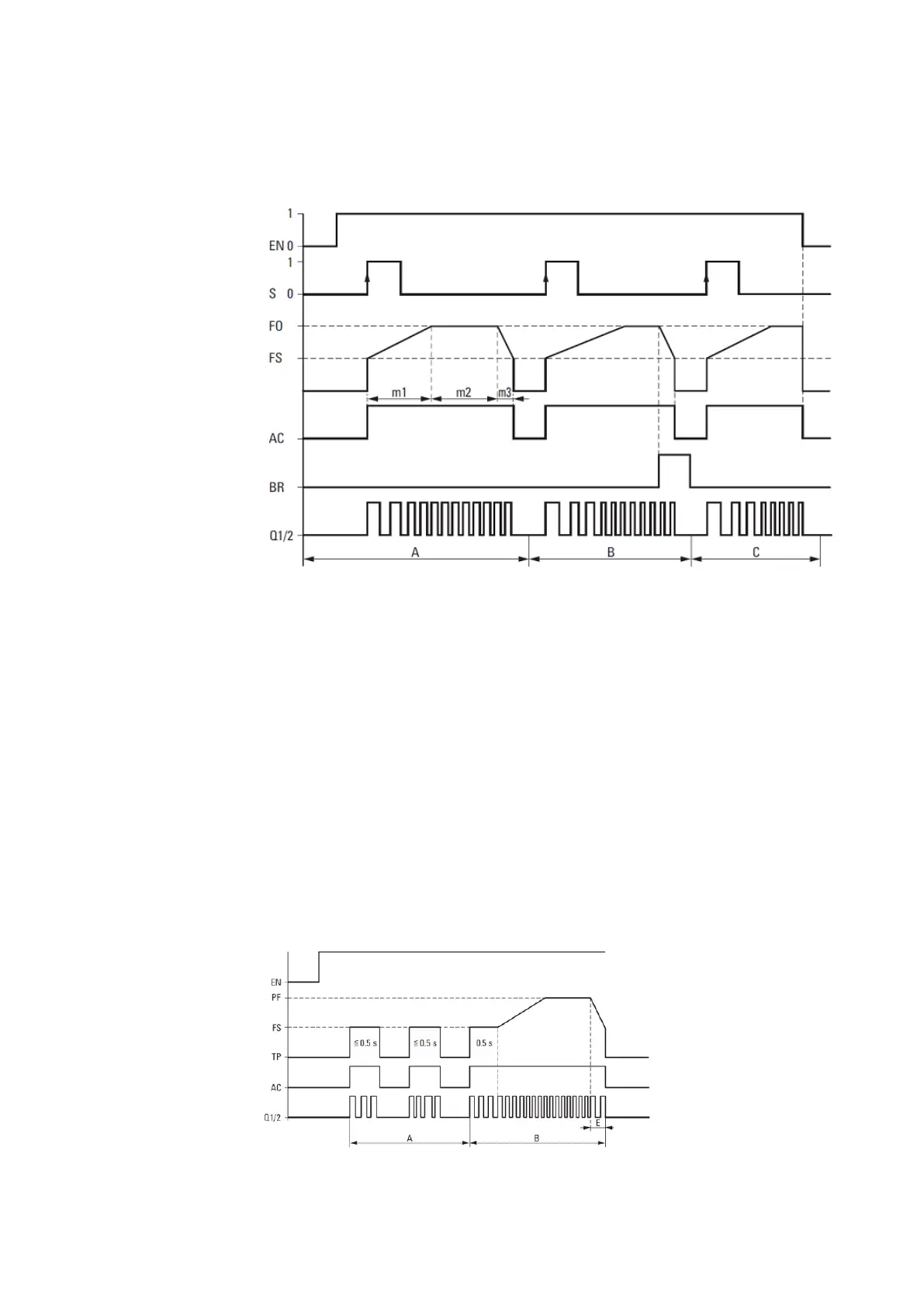
Signal diagram jog mode
Figure 154: Signal diagram PO pulse output - jog mode
292
easyE4 11/18 MN050009 EN www.eaton.com
 Loading...