5. Programming on the device
5.4 Working with contacts and coils
5.4 Working with contacts and coils
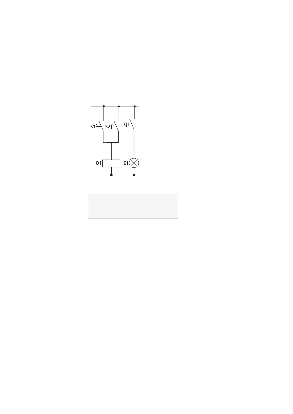
Switches, pushbuttons and relays from a conventional hardwired circuit diagram are
wired in the easyE4 circuit diagram via input contacts and relay coils.
Hardwired Wired with an easyE4 device
easyE4 connection
Make contact S1 to input terminal I1
Make contact S2 to input terminal I2
Connect load E1 to easy output Q1
S1 or S2 switch on E1.
easyE4 circuit diagram:
I 001--------------------Q 001
I 002--k
Figure 77: Circuit diagram with inputs
Circuit diagram with inputs I 001, I 002 and output Q 001
First specify which input and output terminals you wish to use in your circuit.
The signal states on the input terminals are detected in the circuit diagram with the
input contacts I, R or RN. The outputs are switched in the circuit diagram with the out-
put relays Q, S or SN.
The jump destination has a special position for the input contacts and the jump location
for the output relays. These are used for structuring a circuit diagram → Section "Work-
ing with contacts and coils", page 133.
Following is a description of how to wire various contacts and coils for the various
relay types and function blocks (inputs) in the circuit diagram.
easyE4 11/18 MN050009 EN www.eaton.com
133
 Loading...