2. Installation
2.4 Connection terminals
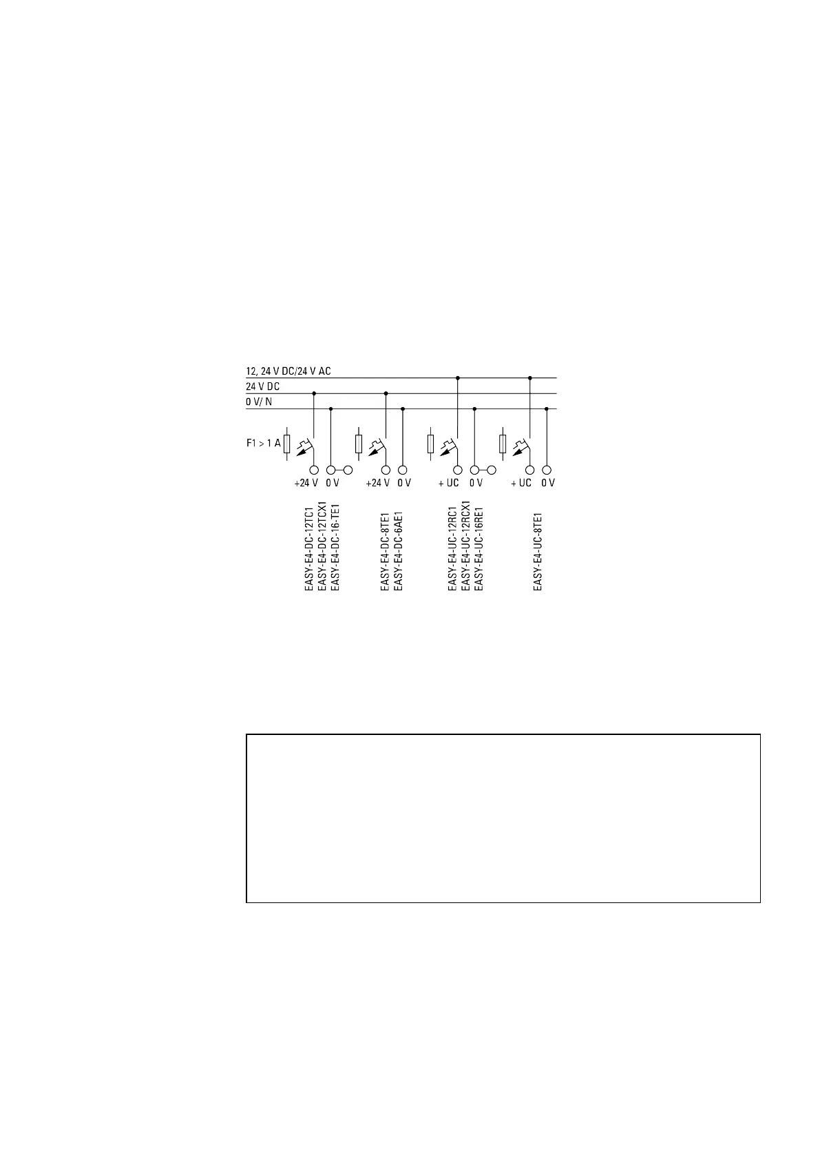
2.4.2 Connecting the power supply
Cable protection
For all base devices, as well as for the expansion devices, connect an (F1) circuit pro-
tection device rated for at least 1 A (slow).
You can use a shared circuit protection device for the base device and expansion(s).
Figure 13: Connecting the power supply
System test
The devices run a system test after the supply voltage has been switched on.
The system test lasts 1 s for the base device. After this time elapses, the device will
enter RUN or STOP mode depending on the specific device and configured settings.
NOTICE
When the basic devices and expansion units are switched on, they
behave like a capacitor, so that an inrush current higher than the rated
input current is present. Take this inrush current into account when
designing the electrical equipment by using slow fuses and suitable
switches. Never use reed relay contacts to switch the power supply
as these may burn or stick. When designing the DC power supply unit,
bear the inrush current in mind.
You can find the required connection specifications for your device model from the cor-
responding data sheet, → Section "Technical data", page 584
easyE4 11/18 MN050009 EN www.eaton.com
49
 Loading...