6. Function blocks
6.2 Interrupt function blocks
The time between the moment the triggering signal is detected and the moment there is
a response at an output is < 1 ms. If multiple interrupts are executed simultaneously,
the times add up.
Measuring the interrupt load
The runtime for each interrupt source is measured in µs. All measured times are added
over a period of 100 ms. After each 100 ms, the total of all times is evaluated and the
time measurement is cleared. If the interrupts used up more than 50% of the computing
time, the application will be stopped.
The <System_CPU_overload> diagnostic message will be generated and ID19 will be
set to 1.
For more information on how diagnostic messages can be called and processed,
please refer to Processing diagnostic messages
Available fixes for high interrupt loads
If the interrupt load becomes too heavy, the following steps can be taken to reduce it:
l Reduce the number of function blocks
l Keep the interrupt routine as short as possible
l Reduce frequencies when using counters
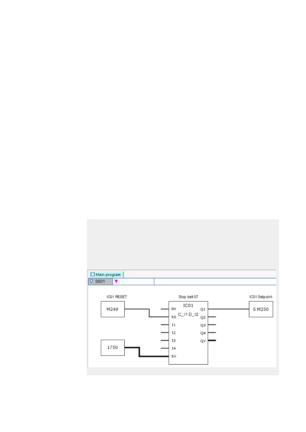
Example of a pulse counter with external direction control in easySoft 7
Device input I1: Counter input C_
Device input I5: Counting direction D_
If the setpoint of <1750> is reached at device input I1, the system will jump to the inter-
rupt program. Inside the interrupt program, QP04 will be used to set device output Q4 to
1 directly. Q01 will be used to set function block output Q1 to 1. The system will then
jump back to the main program.
Figure 188: easySoft 7 main program
412
easyE4 11/18 MN050009 EN www.eaton.com