6. Function blocks
6.1 Manufacturer function blocks
Other
Signal diagram
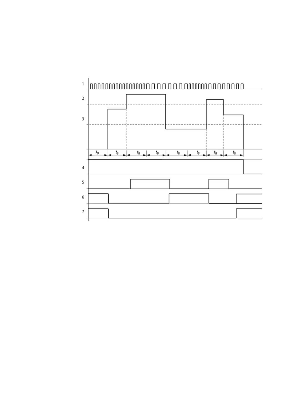
Figure 132: Signal diagram of frequency counter
1: One of the device inputs I01 to I04
2: Upper threshold value SH
3: Lower threshold value SL
4: Enable CF..EN
5: Contact (N/O) CF..OF: Upper threshold value exceeded
6: Contact (N/O) CF..FB: Lower threshold value undershot.
7: Actual value equal to zero CF..ZE
8. tg: gate time ( = measuring interval) for the frequency measurement
The first measurements are made after the CF..EN enable signal has been activated. The value is output
after the gate time has timed out. The contacts are set in accordance with the measured frequency. If
the CF..EN enable signal is removed, the output value is set to zero.
Retention
The frequency counter does not have any retentive actual values since the frequency is
continuously remeasured.
228
easyE4 11/18 MN050009 EN www.eaton.com
 Loading...