HEIDENHAIN MANUALplus 620 251
4.17 Contour-Based Turning Cycles
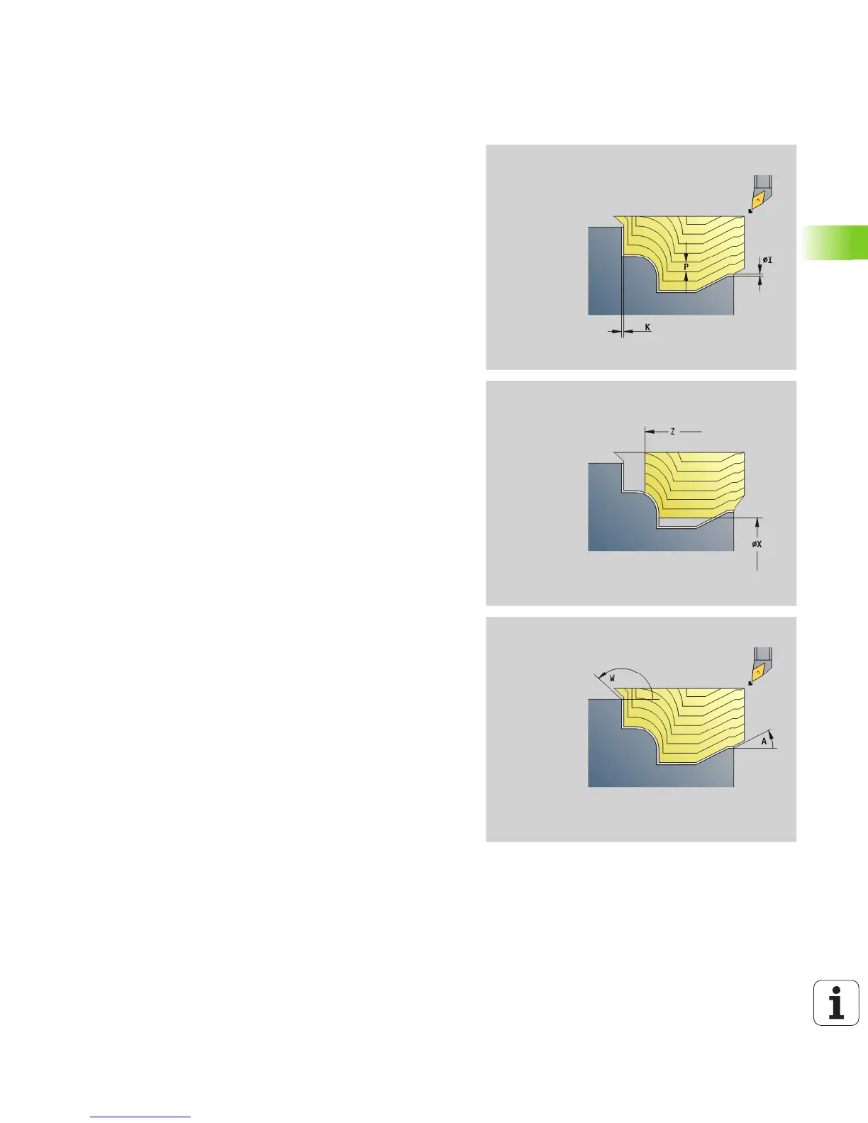
Contour-parallel roughing G830
G830 machines the contour area defined in “ID”, or by "NS, NE",
parallel to the contour (see “Working with contour-based cycles” on
page 246). The contour to be machined may contain various valleys. If
required, the area to be machined is divided into several sections.
Parameters
ID Auxiliary contour—ID number of the contour to be machined
NS Starting block number (beginning of contour section)
NE End block number (end of contour section)
NE not programmed: The contour element NS is machined
in the direction of contour definition.
NS=NE programmed: The contour element NS is machined
opposite to the direction of contour definition.
P Maximum infeed
I Oversize in X direction (diameter value)—(default: 0)
K Oversize in Z direction (default: 0)
X Cutting limit in X direction (diameter value)—(default: no
cutting limit)
Z Cutting limit in Z direction (default: no cutting limit)
A Approach angle (reference: Z axis)—(default: 0°/180°, parallel
to Z axis, or with facing tools: parallel to X axis)
W Departure angle (reference: Z axis)—(default: 90°/270°,
perpendicular to Z axis, or with facing tools: perpendicular to
X axis)
Q Type of retraction at cycle end (default: 0)
0: Returns to starting point, first X, then Z direction
1: Positions in front of the finished contour
2: Retracts to safety clearance and stops
V Identifier start/end (default: 0) A chamfer/rounding arc is
machined:
0: At start and end
1: At beginning
2: At end
3: No machining
4: Chamfer/rounding arc is machined—not the basic
element (prerequisite: Contour section with one element)
B Contour calculation
0: Automatic
1: Tool to the left (G41)
2: Tool to the right (G42)

 Loading...


