272 ISO Programming
4.19 Thread Cycles
Thread cycle G31
G31 machine simple threads, successions of threads and multi-start
threads with G24-Geo, G34-Geo or G37-Geo. G31 can also machine a
threading contour defined directly after the cycle call and concluded by
G80.
Example: G31
. . .
FERTIGTEIL [FINISHED PART]
N 2 G0 X16 Z0
N 3 G52 P2 H1
N 4 G95 F0.8
N 5 G1 Z-18
N 6 G25 H7 I1.15 K5.2 R0.8 W30 BF0 BP0
N 7 G37 Q12 F2 P0.8 A30 W30
N 8 G1 X20 BR-1 BF0 BP0
N 9 G1 Z-23.8759 BR0
N 10 G52 G95
N 11 G3 Z-41.6241 I-14.5 BR0
N 12 G1 Z-45
Parameters
ID Auxiliary contour—ID number of the contour to be machined
NS Contour start block number (reference to basic element G1-
Geo; for successions of threads: block number of the first
basic element)
NE Contour end block number (reference to basic element G1-
Geo; for successions of threads: block number of the last
basic element)
O Identifier start/end (default: 0) A chamfer/rounding arc is
machined:
0: No machining
1: At the start
2: At the end
3: At start and end
4: Chamfer/rounding arc is machined—not the basic
element (prerequisite: Contour section with one element)
J Reference direction:
No input: The reference direction is determined from the
first contour element.
J=0: Longitudinal thread
J=1: Transverse thread
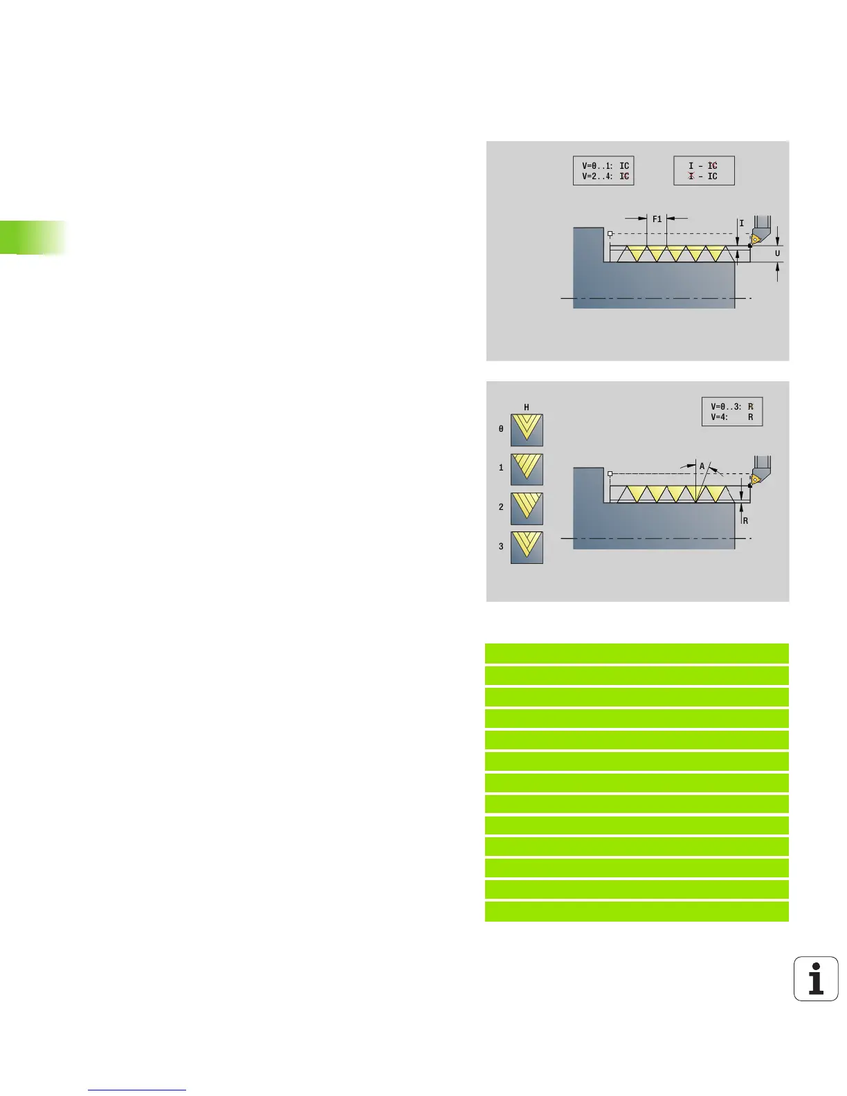
I Approach feed (maximum infeed)
No input and V=0 (constant chip cross section):
I = 1/3 * F
IC Number of cuts. The infeed is calculated from IC and U.
Usable with:
V=0 (constant chip cross section)
V=1 (constant infeed)
B Run-in length
No input: The run-in length is determined from the contour. If
this is not possible, the value is calculated from the kinematic
parameters. The thread contour is extended by the value B.
P Overflow length (run-out length)
No input: The run-out length is determined from the contour.
If this is not possible, the value is calculated. The thread
contour is extended by the value P.
A Approach angle (angle of infeed) (default: 30°)

 Loading...


