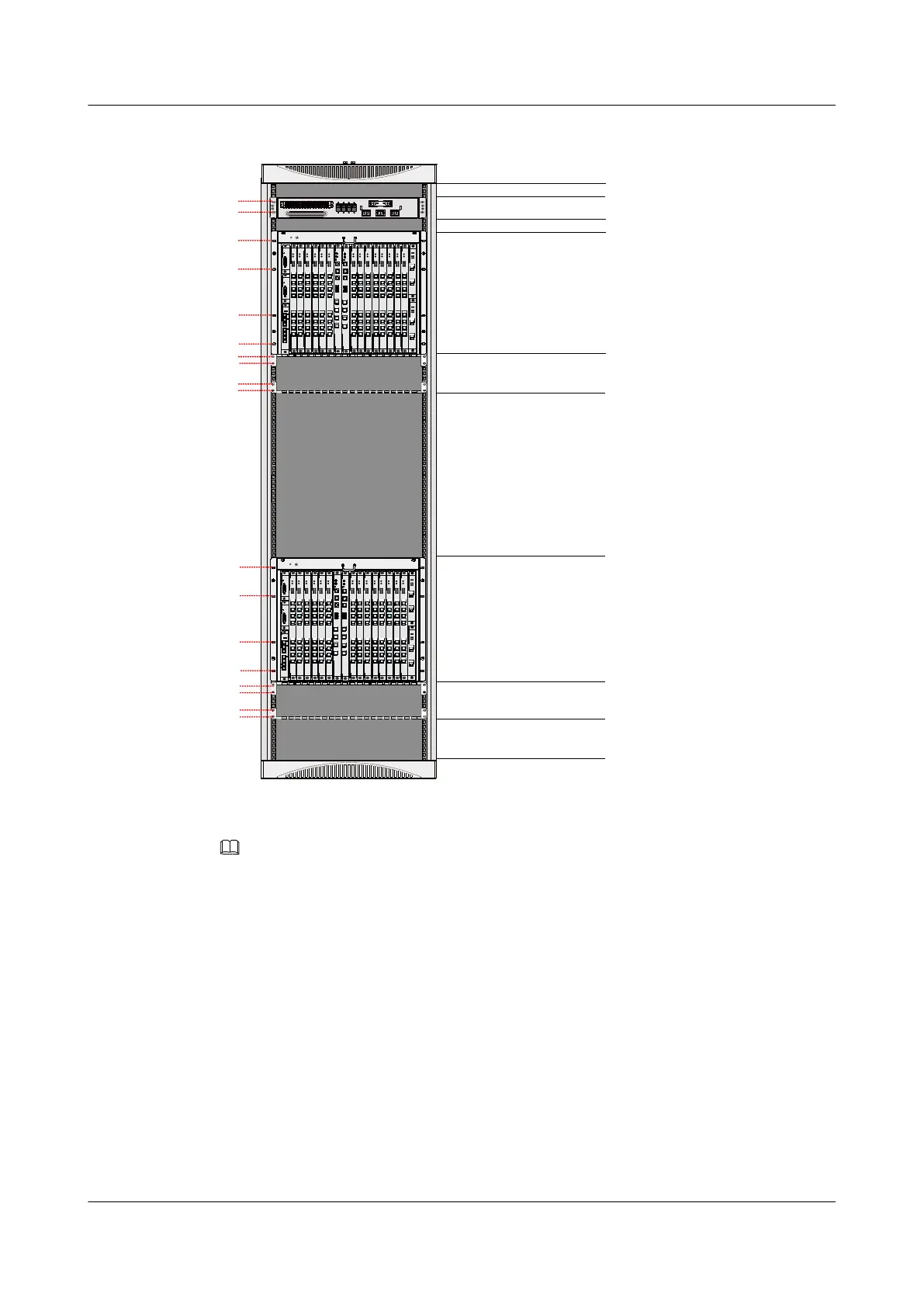
Figure 1-50 Configuration of the N66E-22 cabinet installed with two service shelves
Empty (1U)
C3-Type DC PDU(2U)
IEC Service Subrack2
(10U)
Cabling teeth(3U)
Empty(13U)
Empty (1U)
Cabling teeth(3U)
Empty(3U)
10
12
STAT US
F AN
PRT E
RTN(+)
ALAR M
NEG(-)
PRT E
RTN(+)
ALAR M
NEG(-)
X2CS
RUN
ALM
TX0
RX0
LINK ACT
1
0
TX1
RX1
X2CS
RUN ALM
TX0
RX0
LINK ACT
1
0
TX1
RX1
SC UN
RUN
ALM
ACT
RES E T
LINK A CT
1
0
2
3
C
O
N
E
T
H
E
S
C
TX0
RX 0
TX1
RX 1
TX2
RX 2
TX3
RX3
SCU N
RUN
ALM
ACT
RES E T
LINK AC T
1
0
2
3
C
O
N
E
T
H
E
S
C
TX 0
RX 0
TX 1
RX 1
TX2
RX 2
TX 3
RX 3
CITD
R
U
N
M
A
J
M
I
N
I
N
0
O
U
T
C
O
M
A
L
M
E
T
H
I
N
1
B
I
T
S
/T
O
D
GPBD
RUN
ALM
BSY
PON
0
2
4
6
1
3
5
7
0
1
2
3
4
5
6
7
GPBD
RUN
ALM
BSY
PON
0
2
4
6
1
3
5
7
0
1
2
3
4
5
6
7
GPBD
RUN
ALM
BSY
PON
0
2
4
6
1
3
5
7
0
1
2
3
4
5
6
7
GPBD
RUN
ALM
BSY
PON
0
2
4
6
1
3
5
7
0
1
2
3
4
5
6
7
GPBD
RUN
ALM
BSY
PON
0
2
4
6
1
3
5
7
0
1
2
3
4
5
6
7
GPBD
RUN
ALM
BSY
PON
0
2
4
6
1
3
5
7
0
1
2
3
4
5
6
7
GPBD
RUN
ALM
BSY
PON
0
2
4
6
1
3
5
7
0
1
2
3
4
5
6
7
GPBD
RUN
ALM
BSY
PON
0
2
4
6
1
3
5
7
0
1
2
3
4
5
6
7
GPBD
RUN
ALM
BSY
PON
0
2
4
6
1
3
5
7
0
1
2
3
4
5
6
7
GPBD
RUN
ALM
BSY
PON
0
2
4
6
1
3
5
7
0
1
2
3
4
5
6
7
GPBD
RUN
ALM
BSY
PON
0
2
4
6
1
3
5
7
0
1
2
3
4
5
6
7
GPBD
RUN
ALM
BSY
PON
0
2
4
6
1
3
5
7
0
1
2
3
4
5
6
7
GPBD
RUN
ALM
BSY
PON
0
2
4
6
1
3
5
7
0
1
2
3
4
5
6
7
GPBD
RUN
ALM
BSY
PON
0
2
4
6
1
3
5
7
0
1
2
3
4
5
6
7
STAT US
F AN
PRT E
RTN(+)
ALAR M
NEG(-)
PRT E
RTN(+)
ALAR M
NEG(-)
X2CS
RUN
ALM
TX0
RX0
LINK ACT
1
0
TX1
RX1
X2CS
RUN ALM
TX0
RX0
LINK ACT
1
0
TX1
RX1
SCU N
RUN
ALM
ACT
RES E T
LINK AC T
1
0
2
3
C
O
N
E
T
H
E
S
C
TX 0
RX 0
TX 1
RX 1
TX2
RX 2
TX 3
RX 3
SC UN
RUN
ALM
ACT
RES E T
LINK A CT
1
0
2
3
C
O
N
E
T
H
E
S
C
TX0
RX 0
TX1
RX 1
TX2
RX 2
TX3
RX3
CITD
R
U
N
M
A
J
M
I
N
I
N
0
O
U
T
C
O
M
A
L
M
E
T
H
I
N
1
B
I
T
S
/T
O
D
GPBD
RUN
ALM
BSY
PON
0
2
4
6
1
3
5
7
0
1
2
3
4
5
6
7
GPBD
RUN
ALM
BSY
PON
0
2
4
6
1
3
5
7
0
1
2
3
4
5
6
7
GPBD
RUN
ALM
BSY
PON
0
2
4
6
1
3
5
7
0
1
2
3
4
5
6
7
GPBD
RUN
ALM
BSY
PON
0
2
4
6
1
3
5
7
0
1
2
3
4
5
6
7
GPBD
RUN
ALM
BSY
PON
0
2
4
6
1
3
5
7
0
1
2
3
4
5
6
7
GPBD
RUN
ALM
BSY
PON
0
2
4
6
1
3
5
7
0
1
2
3
4
5
6
7
GPBD
RUN
ALM
BSY
PON
0
2
4
6
1
3
5
7
0
1
2
3
4
5
6
7
GPBD
RUN
ALM
BSY
PON
0
2
4
6
1
3
5
7
0
1
2
3
4
5
6
7
GPBD
RUN
ALM
BSY
PON
0
2
4
6
1
3
5
7
0
1
2
3
4
5
6
7
GPBD
RUN
ALM
BSY
PON
0
2
4
6
1
3
5
7
0
1
2
3
4
5
6
7
GPBD
RUN
ALM
BSY
PON
0
2
4
6
1
3
5
7
0
1
2
3
4
5
6
7
GPBD
RUN
ALM
BSY
PON
0
2
4
6
1
3
5
7
0
1
2
3
4
5
6
7
GPBD
RUN
ALM
BSY
PON
0
2
4
6
1
3
5
7
0
1
2
3
4
5
6
7
GPBD
RUN
ALM
BSY
PON
0
2
4
6
1
3
5
7
0
1
2
3
4
5
6
7
88
90
94
96
99
106
117
124
16
18
21
28
39
46
IEC Service Subrack1
(10U)
RTN1( +)
RTN2 (+)PGND
NEG1 (- )
NEG2 (- )
SW1 SW2 SW3
OFF
OFF OFF
ONON ON
SW4
OFF
ON
131
134
NOTE
In Figure 1-50, the filled holes are for floating nuts to fasten subracks.
1.3.4 Cable Hole
The power cables and subscriber cables are led into the N66E-22 cabinet from the top and the
bottom of the cabinet. This topic describes the positions of cable holes at the top and the
bottom of the N66E-22 cabinet.
The cables of the N66E-22 cabinet can be routed in the overhead cabling mode or the
underfloor cabling mode.
l In the overhead cabling mode, external cables are led into the cabinet through the top of
the cabinet. Figure 1-51 shows the positions of cable holes at the top of the cabinet.
l In the underfloor cabling mode, external cables are led into the cabinet through the
bottom of the cabinet. Figure 1-52 shows the positions of cable holes at the bottom of
the cabinet.
SmartAX MA5600T/MA5603T/MA5608T Multi-service
Access Module
Hardware Description
1 Cabinet
Issue 24 (2018-07-30) Huawei Proprietary and Confidential
Copyright © Huawei Technologies Co., Ltd.
59

 Loading...