Home
Hyundai
Automobile
Tiburon 2003
Hyundai Tiburon 2003 User Manual
5
of 1
of 1 rating
882 pages
Give review
Manual
Specs
To Next Page
To Next Page
To Previous Page
To Previous Page
Loading...
TIBURO
N(GK
) > 20
03 > G
2.7 V
6 DOH
C > B
ody (Int
erior a
nd Ext
erio
r) > Int
erior > c
rash
pad >
Repair
proce
dures,
TIBURO
N(GK
) > 20
03 > G
2.7 V
6 DOH
C > B
ody (Int
erior a
nd Ext
erio
r) > Int
erior >
crash
pad
> Repa
ir proc
edures
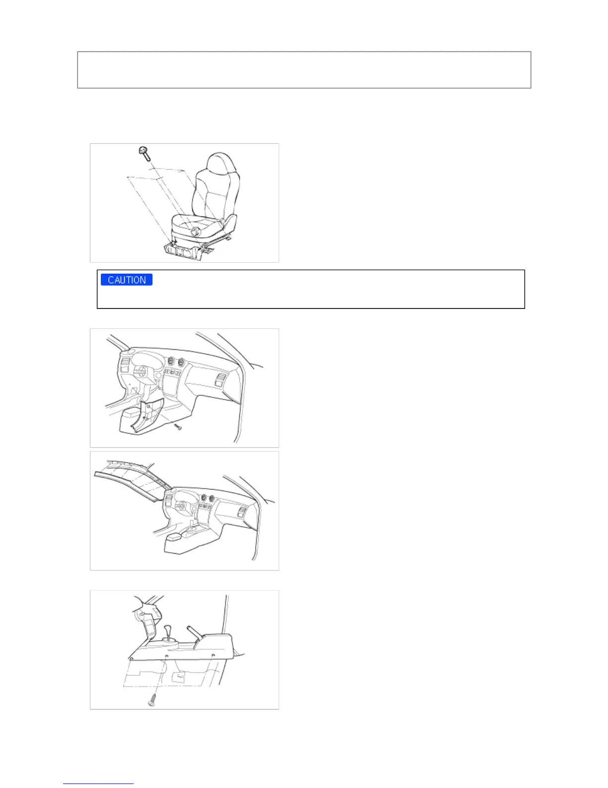
REMOVAL AND INSTALLATION
1.
Disc
onnect
the neg
ative b
attery
temin
al.
2.
Disc
onnect
the wi
re conne
ctors
from
the fron
t seat
s and th
en rem
ove t
he front
seats.
Take ca
re not
to scr
atch the
trim
when re
movin
g the fr
onts s
eats.
3.
Remo
ve the
cowl
side tr
im, front
pillar
.
4.
Remo
ve the
conso
le asse
mbly.
5.
Remo
ve the
air ba
g modu
le.
Page
1
of
5
24.04.2008
http://www.hmaservice.com/viewer/content.asp?IsPrint=true&imgnum=1&print_title
...
721
723
Table of Contents
Vehicle Identification Number
1
Identification Number Locations/Decription
1
Engine Identification Number
2
Transmission Identification Number
3
Automatic
3
Warning/Caution Label Locations
4
Emission Control Label
7
Lift and Support Point
8
Towing
9
Tightening Torque Table of Standard Parts
10
Recommended Lubricants
11
Lubricants Capacities
11
Selection of Engine Oil
12
General Service Information
12
Special Tools
12
Recommended SAE Viscosity Grades
12
Removal of Parts
13
Disassembly
13
Electrical System
14
Rubber Parts and Tubes
15
Measuring Body Dimensions
15
Projected Dimensions
15
Measuring Actual Dimensions
15
Checking Cables and Wires
16
Check Fuses
16
Servicing the Electrical System
16
Precautions for Catalytic Converter
19
The Micro 570 Analyzer
21
Keypad
21
Battery Test Procedure
21
Battery Test Results
23
Starter Test Procedure
23
Charging System Test Procedure
24
Starter Test Results
24
Charging System Test Results
26
Troubleshooting
27
Specification
29
Auto Cruise Control System
30
Tightening Torque
30
On-Vehicle Inspection
32
Inspect Spark Test
32
Inspect Spark Plug and Spark Plug Cable
32
Inspect Ignition Coil
34
Circuit Diagram for Charging System
36
Check Battery Voltage
39
Check Battery Terminals, Fusible Link and Fuses
39
Inspect Drive Belt
39
Visually Check Generator Wiring and Listen for Abnormal Noises
40
Check Discharge Warning Light Circuit
40
Inspect Charging System
40
Components
45
Alternator Belt Inspection and Adjustment
48
Battery Diagnostic Test
52
Circuit Diagram for Starting System
55
Start Test
57
Check the Starter Engagement
57
Starter Solenoid Test
58
Free Running Test
58
Circuit Diagram for Cruise Control System
63
Functions of Individual Switches
64
Auto Cancellation
64
Components Location
65
Brake Switch Test
67
Cruise Control Switch Test
67
Actuator Cable Adjustment
68
Change Engine Oil
76
Replacement Oil Filter
77
Radiator Cap Pressure Test
78
Specific Gravity Test
78
Checking Compression Pressure
79
Tightening Cylinder Head Bolts
80
Adjusting Valve Clearance
80
Adjusting Drive Belt and Tensioner
80
How to Adjust the Tension of the Timing Belt
91
Oil Seal (Camshaft Front)
95
HLA (Hydraulic Lash Adjuster)
95
Timing Chain
96
Valve Guides
102
Valve
103
Valve Spring
104
Replacing Valve Guide
104
Replacing Valve Seat Ring
105
Connecting Rod Cap
115
Disassembly and Reassembly of the Piston Pin
115
Pistons and Piston Pins
116
Piston Rings
116
Connecting Rods
117
Main Bearings and Connecting Rod Bearings
122
Measuring Oil Clearance
122
Plastic Gauge Method
123
Oil Seal
123
Main Bearing
123
Cylinder Block
128
Boring Cylinder
129
Engine Mounting
132
Transaxle Mounting
132
Front Roll Stopper
132
Rear Roll Stopper
133
Cooling System
134
Inlet Control
134
Flow Chart
134
Cooling System Components
135
Coolant Temperature Sensor Replacement
145
Oil Pump
148
Relief Plunger and Spring
149
Oil Filter Bracket
149
Oil Pressure Switch
149
Air Cleaner Components
153
Air Cleaner Removal
154
Air Cleaner Installation
154
Air Cleaner Inspection
154
Intake Manifold Components
156
Intake Manifold Removal
157
Intake Manifold Installation
159
Intake Manifold Inspection
159
Surge Tank and Intake Manifold
159
Exhaust Manifold Components
161
Exhaust Manifold Removal/Installation
162
Exhaust Manifold Inspection
162
Muffler Components
164
Muffler Removal/Installation
165
Muffler Inspection
165
Front Exhaust Pipe (Including Catalytic Converter)
165
Emission Control System Schematic Drawing
166
Vacuum Hoses Layout
167
Emission Control System Components
168
Emission Control System Troubleshooting
169
Emission Control System Specifications
170
Crankcase Emission Control System Components
171
Positive Crankcase Ventilation (PCV) Valve Operation
172
Positive Crankcase Ventilation (PCV) Valve Removal/Installation
173
Positive Crankcase Ventilation (PCV) Valve Inspection
173
Evaporative Emission Control System Components
174
Evaporative Emission Control System Description
175
Evaporative Emission Control System Inspection
176
Check of Canister Close Valve Operating
176
Air Filter
177
Purge Control Solenoid Valve (PCSV) Inspection
178
EVAP Canister Purge Solenoid Valve
178
Vacuum Hose
179
Fuel Tank Pressure Sensor (FTPS) Inspection
181
Fuel Filler Cap Operation
182
Fuel System Special Tools
183
Multiport Fuel Injection (MFI) General Information
184
Fuel Injection Control
184
Idle Speed Control
184
Ignition Timing Control
184
Service Points in Inspecting a Blown Fuse
185
Inspecting the MFI System
185
On-Board Diagnostics
185
Fuel System Troubleshooting
188
Scan Tool Communication with PCM Is Not Possible
191
Engine will Not Start
191
Difficult to Start (Engine Cranks)
191
Rough Idle or Engine Stalls
193
Engine Hesitates or Accelerates Poorly
195
Fuel System General Specifications
198
Fuel System Service Standard
198
Fuel System Tightening Torque
199
Fuel System Sealant
199
Inspection Chart for Diagnostic Trouble Codes
200
Trouble Area Related to DTC
202
Major Sensor Reference Wave-Forms
213
Location of MFI Components
214
Suspension System Special Tools
217
Suspension System Troubleshooting
219
Wheel and Tire Diagnosis
219
Suspension System Specifications
221
Suspension System Service Standard
222
Suspension System Tightening Torque
223
Suspension System Lubricants
223
Suspension System Components
224
Front Strut Assembly Removal/Installation
225
Front Strut Assembly Disassembly
226
Front Strut Assembly Inspection
226
Front Strut Assembly Disposal
227
Front Strut Assembly Reassembly
227
Front Lower Arm Components
229
Front Lower Arm Removal/Replacement
230
Ball Joint and Dust Cover
230
Lower Arm Bushing
231
Front Lower Arm Installation
232
Front Lower Arm Inspection
232
Front Stabilizer Bar Components
234
Front Stabilizer Bar Removal/Installation
235
Front Stabilizer Bar Inspection
236
Rear Strut Assembly Components
237
Rear Strut Assembly Removal/Disassembly
238
Rear Strut Assembly Inspection
239
Rear Strut Assembly Reassembly
239
Rear Suspension Arm Components
241
Rear Suspension Arm Removal/Installation
242
Rear Suspension Arm Inspection
243
Trailing Arm Removal/Replacement
244
Trailing Arm Bushing
244
Rear Suspension Arm Bushing
245
Rear Stabilizer Bar Removal/Installation
246
Rear Stabilizer Bar Inspection
247
Tires/Wheels Description
248
Front Wheel Alignment
249
Rear Wheel Alignment
250
Tire Wear
250
Wheel Rotation
252
Checking for Pull and Wander
252
Wheel Runout
253
Tightening Wheel Nut
253
Driveshaft and Axle Special Tools
256
Driveshaft and Axle Troubleshooting
258
Driveshaft and Axle Specifications
259
Driveshaft and Axle Tightening Torque
259
Driveshaft and Axle Lubricants
260
Front Driveshaft Components
261
Front Driveshaft Removal
264
Front Driveshaft Installation
265
Front Driveshaft Inspection
266
Front Driveshaft Disassembly
267
Front Driveshaft Reassembly
269
Center Bearing and Inner Shaft Components (2.7L)
272
Center Bearing and Inner Shaft Disassembly
273
Center Bearing and Inner Shaft Reassembly
273
Front Hub / Axle Components
275
Front Hub / Axle Removal/Installation
276
Front Hub / Axle Disassembly
277
Front Hub / Axle Inspection
278
Front Hub / Axle Reassembly
278
Rear Hub / Carrier Components
281
Rear Hub / Carrier Removal/Installation
282
Rear Hub / Carrier Inspection
283
Brake System Precaution
284
Brake System Special Tools
285
Brake System Component Locating Index
286
Brake System Troubleshooting
287
Brake System Operation and Leakage Check
288
Brake Pedal and Brake Switch Adjustment
289
Pedal Height
289
Brake Switch Clearance
289
Pedal Free Play
289
Parking Brake Check and Adjustment
290
Brake System Bleeding
291
Front/Rear Disc Brake
292
Brake System Specifications
293
Brake System Service Standard
294
Brake System Tightening Torque
294
Brake Booster Components
295
Brake Booster Removal/Installation
296
Master Cylinder Component
298
Master Cylinder Removal/Installation
299
Master Cylinder Disassembly
299
Master Cylinder Inspection
300
Master Cylinder Reassembly
300
Proportioning Valve Removal/Installation
303
Proportioning Valve Inspection
303
Brake Line Components Location
304
Brake Line Inspection
305
Brake Line Replacement
305
Brake Pedal Components
307
Brake Pedal Removal/Installation
308
Brake Pedal Inspection
308
Front Disc Brake Components
310
Front Disc Brake Replacement
311
Brake Pad Removal/Installation
311
Brake Pad Inspection
311
Front Disc Brake Removal/Installation
313
Front Disc Brake Disassembly
313
Front Disc Brake Inspection
314
Front Disc Brake Reassembly
315
Rear Disc Brake General Information
317
Rear Disc Brake Components
318
Rear Disc Brake Replacement
320
Rear Disc Brake Inspection
322
Rear Disc Brake Thickness and Parallelism
322
Parking Brake Assembly Components
324
Parking Brake Assembly Removal
325
Abs(Anti-Lock Brake System) Hydraulic System Diagram
326
Abs(Anti-Lock Brake System) Circuit Diagram
326
Abs(Anti-Lock Brake System) Description
329
Abs(Anti-Lock Brake System) Operation
329
Abs(Anti-Lock Brake System) Warning Lamp Control
329
Abs(Anti-Lock Brake System) Diagnostic Trouble Code (DTC)
330
Abs(Anti-Lock Brake System) Self-Diagnosis
330
How to Troubleshoot ABS DTC
330
Hi-Scan (Pro) Check
330
Abs(Anti-Lock Brake System) System Function
331
Traction Control System (TCS) Operation
332
Traction Control System (TCS) Function
332
Full Traction Control System (FTCS)
333
Brake Traction Control System (BTCS)
333
EBD (Electronic Brake-Force Distribution) Operation
333
Comparison between Proportioning Valve and EBD
334
Abs(Anti-Lock Brake System) Components
335
Abs(Anti-Lock Brake System) Troubleshooting
336
Abs(Anti-Lock Brake System) Check Sheet
336
Abs(Anti-Lock Brake System) Diagnostic Trouble Code Chart
338
Failsafe Specification
338
The Management of Failure Detection
338
Inspection Procedure for Diagnostic Trouble Codes
346
Bleeding of Brake System
360
HECU Block Diagram
363
HECU Circuit Diagram
364
Inspection of HECU Terminals
365
ABS Control Module Components
367
ABS Control Module Removal
369
ABS Control Module Installation
370
ABS Control Module Inspection
370
Wheel Speed Sensor Output Voltage Check
370
Front Wheel Speed Sensor Components
372
Front Wheel Speed Sensor Removal
373
Rear Wheel Speed Sensor
373
Manual Transaxle System Special Tools (6-Speed M/T)
375
Manual Transaxle System Troubleshooting (M/T)
376
Manual Transaxle System Specifications (M/T)
377
Manual Transaxle System Service Standard (6-Speed M/T)
377
Manual Transaxle System Tightening Torque (6-Speed M/T)
377
Manual Transaxle System Removal
378
Manual Transaxle System Installation
387
Manual Transaxle System Service Adjustment Procedures
387
Transaxle Gear Oil Level Inspection /Replacement
387
Drive Shaft Oil Seal Replacement
387
Manual Transaxle Shift Control Components
388
Manual Transaxle Shift Control Removal
390
Manual Transaxle Shift Control Installation
392
Manual Transaxle Shift Control Inspection
392
Automatic Transaxle Shift Control Special Tools
393
Automatic Transaxle Shift Control Specifications
394
Automatic Transaxle System TCM Circuit Diagram
395
Automatic Transaxle System Hydraulic Circuit Park & Neutral
401
Automatic Transaxle System Troubleshooting
407
Automatic Transaxle System Diagnosis Function
407
Automatic Transaxle System Road Test
408
Automatic Transaxle System Inspection Chart for Diagnosis Codes
411
Automatic Transaxle System Inspection Chart for Trouble Symptoms
414
Automatic Transaxle System Elements in Use in each Gear
416
Automatic Transaxle System Operating Elements and Their Function
416
Automatic Transaxle System Inspection Process for Trouble Symptoms
418
Automatic Transaxle System Basic Inspection Adjustment
426
Automatic Transaxle System Fluid Check
426
Automatic Transaxle Fluid
426
Transaxle Range Switch Continuity Check
427
Transaxle Range Switch and Control Cable Adjustment
427
A/T Control Component Check
428
Vehicle Speed Sensor Check
429
A/T Control Relay Check
429
Solenoid Valve Check
429
Brake Reaction Plate End Play Adjustment
436
Second Brake End Play Adjustment
436
Low-Reverse Brake End Play Adjustment
436
Underdrive Sun Gear End Play Adjustment
437
Differential Case Preload Adjustment
438
Automatic Transaxle Components
439
Automatic Transaxle Removal
440
Automatic Transaxle Installation
448
Transaxle Shift Control Components
449
Transaxle Shift Control Removal
450
Procedure to Install the Lock Cam
452
Procedure for Adjusting Shift Lock and Key Lock Cable
453
Procedure for Checking the Shift Lock
454
Clutch System Special Tools
455
Clutch System Troubleshooting
456
Clutch System Specifications
458
Clutch System Service Standard
458
Clutch System Tightening Torque
458
Clutch System Lubricants
458
Clutch Cover and Dinode Components
460
Clutch Cover and Dinode Removal/Installation
461
Clutch Cover Assembly
463
Clutch Disc
463
Clutch Release Bearing
464
Clutch Release Fork
464
Clutch Master Cylinder Components
465
Clutch Master Cylinder Disassembly
466
Clutch Master Cylinder Inspection
466
Clutch Master Cylinder Reassembly
466
Clutch Pedal Components
468
Clutch Pedal Removal/Installation
469
Clutch Pedal Inspection
469
Ignition Lock Switch Inspection
469
Clutch Release Cylinder Components
471
Clutch Release Cylinder Removal/Installation
472
Clutch Release Cylinder Inspection
472
Clutch Release Cylinder Disassembly
472
Clutch Release Cylinder Reassembly
473
Clutch Pedal Inspection and Adjustment
474
Bleeding
475
Checking Steering Wheel Free Play
476
Checking Steering Angle
476
Checking the Tie Rod End Ball Joint Starting Torque
476
Checking Stationary Steering Effort
477
Checking Steering Wheel Return
478
Checking Power Steering Belt Tension
478
Checking Power Steering Fluid Level
479
Replacing Power Steering Fluid
479
Air Bleeding
480
Oil Pump Pressure Test
481
Steering System Special Tools
483
Steering System Troubleshooting
485
Steering System Specifications
486
Steering System Service Standard
486
Steering System Tightening Torque
486
Steering System Lubricants
486
Power Steering Gear Box Components
488
Power Steering Gear Box Disassembly and Assembly
488
Power Steering Gear Box Removal
490
Power Steering Gear Box Installation
491
Power Steering Gear Box Disassembly
492
Power Steering Gear Box Inspection and Adjustment before Disassembly
496
Total Pinion Preload
496
Tie Rod Swing Resistance
497
Bellows Inspection
497
Power Steering Hoses Components
504
Power Steering Hoses Removal/Installation
505
Pressure Hose and Tube
505
Return Tube and Hose
506
How to Fill with Power Steering Fluid
507
Power Steering Oil Pump Components
508
Power Steering Oil Pump Removal
509
Power Steering Oil Pump Installation
510
Power Steering Oil Pump Disassembly
511
Power Steering Oil Pump Inspection
513
Power Steering Oil Pump Reassembly
514
Refrigeration Cycle
517
Heating,Ventilation, Air Conditioning Precautions
518
Heating,Ventilation, Air Conditioning Special Tools
519
Heating,Ventilation, Air Conditioning Self-Diagnosis
520
Heating,Ventilation, Air Conditioning Control Panel
520
How to Read Self-Diagnostic Code
520
Heating,Ventilation, Air Conditioning Troubleshooting
526
Heating,Ventilation, Air Conditioning On-Vehicle Inspection
528
Heating,Ventilation, Air Conditioning Test Conditions
528
Inspect for Leakage of Refrigerant
532
A/C System Tests
532
Refrigerant Recovery
533
System Evacuation
533
Compressor Component Location
536
Compressor Replacement
539
Compressor Inspection
540
Compressor Disassembly
541
Receiver/Drier Inspection
544
Refrigerant Line Component Location
545
Triple Pressure Switch Schematic Diagrams
547
Triple Pressure Switch Connector
547
Triple Pressure Switch Circuit Diagram
547
Triple Pressure Switch Description
548
In-Car Sensor Description
549
In-Car Sensor Characteristics
549
Photo Sensor Description
550
Ambient Sensor
551
Ambient Sensor Description
552
Ambient Sensor Inspection
553
Ambient Sensor Characteristics
553
A.Q.S (Air Quality Sensor) Description
555
Checking Method of Gas Detecting Bench
556
Heater Unit Component Location
557
Heater Unit Removal
559
Temperature Control Actuator Connector
564
Temperature Control Actuator Description
565
Temperature Control Actuator Component Location
566
Temperature Control Actuator Replacement
567
Mode Control Actuator Connector
568
Mode Control Actuator Description
569
Mode Control Actuator Component Location
570
Mode Control Actuator Replacement
571
Blower Circuit Diagram
572
Blower Unit Component Location
575
Blower Unit Removal
577
Blower Unit Air Filter Replacement
577
Blower Motor Description
580
Blower Motor Component Location
581
Blower Motor Inspection
582
Blower Relay Connector
583
Blower Relay Circuit Diagram
583
Blower Relay Description
584
Blower Relay Component Location
585
Power Transistor Connector
586
Power Transistor Circuit Diagram and Important Performance of Parts Composed Circuit
586
Power Transistor Description
587
Power Transistor Component Location
588
Blower Resistor Connector
589
Blower Resistor Circuit Diagram
589
Blower Resistor Description
590
Blower Resistor Characteristics
590
Blower Resistor Component Location
591
Blower Resistor Inspection
592
Intake Actuator Connector
593
Intake Actuator Circuit Diagram
593
Intake Actuator Description
594
Intake Actuator Component Location
595
Intake Actuator Replacement
596
Control Panel Connector Configurations
597
Control Panel Description
600
Control Panel Components
601
Controller Circuit Diagram
602
Controller Connector Configurations
606
Manual Controller Description
608
Manual Controller Components
616
Manual Controller Control Panel Tests
617
Manual Controller Power Supply Check
617
Back Light and Rear Glass Heat Rays Check
618
Manual Controller Blower Check
619
Manual Controller Air Conditioner Check
620
Intake and AQS Check
621
Manual Controller Mode Check
622
Manual Controller Temp Check
623
Restraint
625
SRSCM (Supplemental Restraints System Control Module)
626
Restraint Special Service Tool
627
SRSCM Connector Dab+Pab+Sab+Bpt
628
SRSCM Diagnostic Troubleshooting Flow
629
SRSCM Independent Lamp Activation
630
Clock Spring
630
Satellite Sensor
630
SRSCM Diagnostic with Scan Tool
631
Air Bag SQUIB Resistance Limits
632
Supplemental Restraint System Control Module (Srnodem) Component and Layout
634
Supplemental Restraint System Control Module (Srnodem) Inspection Chart for Diagnostic Trouble Code
635
Supplemental Restraint System Control Module (Srnodem) Circuit Description
636
Airbag Module Disposal Procedures
670
Undeployed Airbag Module Disposal
670
Deployment Inside the Vehicle
670
Deployed Airbag Module Disposal Procedures
671
Passenger Airbag (PAB) Module Components
678
Passenger Airbag (PAB) Module Removal
679
Side Airbag (SAB) Module Removal
681
Satellite Sensor Removal
682
Seat Belt Pretensioner Removal
683
Body (Interior and Exterior) Special Tools
685
Body (Interior and Exterior) Troubleshooting
686
Body (Interior and Exterior) Specifications
688
Body (Interior and Exterior) Tightening Torque
688
Body (Interior and Exterior) Components
690
Body (Interior and Exterior) Removal/Installation
691
Fender Garnish
691
Body (Interior and Exterior) Adjustment
694
Hood Hinge/Latch
694
Exterior Tail Gate Removal and Installation
695
Exterior Front Door Removal and Installation
698
Door Position
702
Door Striker
702
Exterior Mirror Components
703
Exterior Mirror Removal and Installation
704
Outside/Inside Rearview Mirror
704
Sun Roof Components
706
Sun Roof Removal
708
Sun Roof Disassembly
709
Sun Roof Inspection
716
Sun Roof Moter Inspection
718
Sun Roof Relay Inspection
719
Interior Console Components
720
Interior Console Removal and Installation
721
Crash Pad Removal and Installation
722
Interior Trim Components
727
Interior Trim Removal and Installation
728
Door Scuff Trim and Step Plate Trim
728
Cowl Side Trim
728
Covering Shelf Center Trim and Side Trim
728
Luggage Board Center Trim
731
Luggage Board Front Trim
731
Luggage Side Trim
731
Head Lining
731
Windshield Glass Components
733
Windshield Glass Removal
734
Windshield Glass Installation
735
Tailgate Glass Components
739
Tailgate Glass Components Removal
740
Quarter Glass Components
743
Quarter Glass Removal/Installation
744
Front Bumper Components
747
Bumper Removal and Installation
748
Rear Bumper Components
750
Rear Bumper Removal and Installation
751
Front Seat Belt Components
753
Front Seat Belt Removal and Installation
754
Rear Seat Belt Components
755
Rear Seat Belt Removal and Installation
756
Rear Seat Belt Buckle
757
Body Electrical System General Troubleshooting Information
758
Body Electrical System Troubleshooting
762
Audio Unit Components
781
Audio Unit Removal
785
Audio Unit Auto CD Changer
785
Tape Head and Capstan Cleaning
785
Audio Fault Code
786
Multifunction Switch Components
787
Multifunction Switch Removal
788
Multifunction Switch Inspection
789
Horn Removal
791
Horn Inspection
791
Horn Adjustment
791
Keyless Entry Description
792
BCM Block Diagram
792
Body Control Module (BCM)
793
Keyless Entry Troubleshooting
799
Keyless Entry Removal
804
Keyless Entry Inspection
804
BCM Function
804
Keyless Entry Transmitter Code Saving Method
815
Keyless Entry Programming Transmitter Code
816
Relay Box (Engine Compartment) Components
817
Relay Box (Engine Compartment) Inspection
818
Relay Box (Passenger Compartment) Inspection
821
Relay Box (Passenger Compartment) Inspection of Fuses
821
Instrument Cluster Circuit Diagram
823
Instrument Cluster Components
824
Instrument Cluster Removal
825
Instrument Cluster Inspection
825
Speedometer
825
Tachometer
826
Fuel Gauge
826
Fuel Sender
826
Engine Coolant Temperature Gauge
827
Engine Coolant Temperature Sender
827
Oil Pressure Warning Lamp
828
Brake Fluid Level Warning Switch
828
Brake Fluid Level Warning Lamp
828
Parking Brake Switch
829
Seat Belt Switch
829
Multi Gauge Description
832
Multi Gauge Components
833
Power Door Locks Components
834
Power Door Locks Inspection
835
Door Lock Actuator Inspection
835
Door Lock Switch Inspection
835
Power out Side Mirror Switch Inspection
839
Power Windows Components
841
Power Window Motor Inspection
842
Power Window Switch Circuit Diagram
843
Power Window Switch Inspection
844
Power Window Main Switch
844
Rear Window Defogger Printed Heater Inspection
846
Repair of Broken Heater Line
847
Windshield Wiper/Washer Components
849
Windshield Washer Installation
849
Windshield Wiper/Washer Switch Inspection
851
Front Wiper Motor Removal/Installation
852
Front Washer Motor Inspection
855
Rear Wiper/Washer Components
856
Rear Wiper Motor Removal
857
Rear Wiper Motor Installation
858
Rear Wiper Motor Inspection
858
Rear Washer Switch Inspection
859
Rear Washer Motor Inspection
860
Lighting System Replacement of Lamps
861
Head Lamp/Turn Signal Lamp
861
Front Fog Lamp
861
Rear Combination Lamp
862
License Plate Lamp
863
Overhead Console Lamp
863
Luggage Lamp
863
Head Lamp Relay
864
Hazard Switch
864
Rheostat
865
Front Fog Lamp Switch
865
Map Lamp Switch
865
Head Lamps Aiming Instructions
867
Head Lamps Front Fog Lamp
867
Head Lamp and Fog Lamp Aiming Point
868
Auto Lighting Control System Circuit Diagram
870
Auto Lighting Control System Description
871
Auto Lighting Control System Inspection
872
Daytime Running Lights Circuit Diagram
873
DRL Control Module Inspection
874
DRL Control Module Operation Check
874
DRL Control Module Inspect Circuits for Daytime Running Light System
874
Immobilizer System Description
876
Immobilizer System Block Diagram
876
Immobilizer System Components
880
Diagnosis of Immobilizer Faults
882
5
Based on 1 rating
Ask a question
Give review
Questions and Answers:
Need help?
Do you have a question about the Hyundai Tiburon 2003 and is the answer not in the manual?
Ask a question
Hyundai Tiburon 2003 Specifications
General
Brand
Hyundai
Model
Tiburon 2003
Category
Automobile
Language
English
Related product manuals
Hyundai Tiburon 2000
39 pages
Hyundai Coupe Tiburon 2007
487 pages
Hyundai Coupe Tiburon 2005
478 pages
Hyundai 2008 Tiburon
268 pages
Hyundai 2003 Tiburon
169 pages
Hyundai 2004 Tiburon
224 pages
Hyundai 2005 Tiburon
262 pages
Hyundai 2006 Tiburon
266 pages
Hyundai 2007 Tiburon
269 pages
Hyundai 2001 Tiburon
142 pages
Hyundai Tiburon
266 pages
Hyundai 2003 Elantra
172 pages
 Loading...