S1: Spindles
16.2 Operating modes
Basic Functions
Function Manual, 09/2011, 6FC5397-0BP40-2BA0
1271
16.2.5.3 Positioning from standstill
Procedure
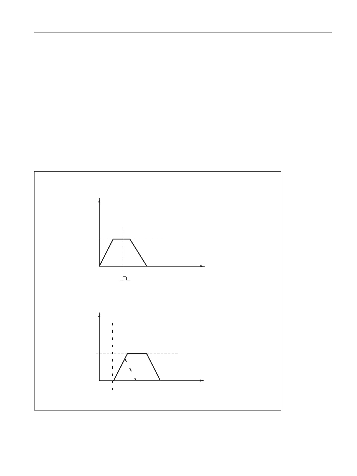
A distinction is made between two cases with regard to positioning from standstill:
• Case 1: The spindle is not synchronized.
This is the case if the spindle is to be positioned after switching on the control and drive or after a gear step
change (e.g. for a tool change).
MD31040 $MA_ENC_IS_DIRECT = 0
• Case 2: The spindle is synchronized.
This is the case if, after switching on the control and drive, the spindle is to be rotated through a minimum of
one revolution with M3 or M4 and then stopped with M5 (synchronization with the zero mark) before the first
positioning action.
Figure 16-2 Positioning with stationary spindle
UHYPLQ
D
D
UHYPLQ
6326>@
0'63,1'B326&75/B9(/2
6326>@
&DVH6SLQGOHQRWV\QFKURQL]HG
7LPHV
=HURPDUN
3RVLWLRQFRQWURODFWLYDWLRQVSHHG
&DVH6SLQGOHV\QFKURQL]HG
6SLQGOHVSHHG
7LPHV
3RVLWLRQFRQWURODFWLYDWLRQVSHHG
6SLQGOHVSHHG
0'63,1'B326&75/B9(/2

 Loading...


