G2: Velocities, setpoint / actual value systems, closed-loop control
7.4 Setpoint/actual-value system
Basic Functions
Function Manual, 09/2011, 6FC5397-0BP40-2BA0
353
7.4 Setpoint/actual-value system
7.4.1 General
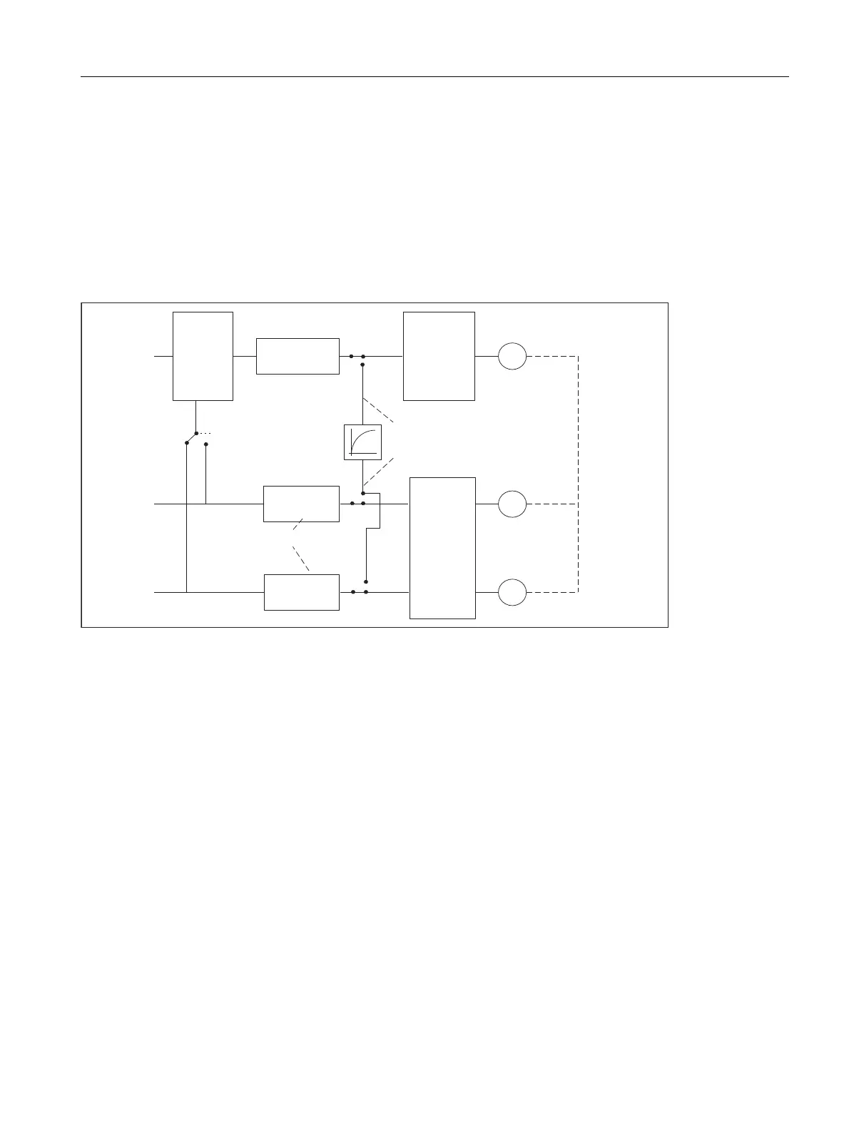
Control loop
A control loop with the following structure can be configured for every closed-loop controlled axis/spindle:
Figure 7-1 Block diagram of a control loop
Setpoint output
A setpoint telegram can be output for each axis/spindle. The setpoint output to the actuator is realized from the
SINUMERIK 840D sl.
Actual-value acquisition
A maximum of two measuring systems can be connected for each axis/spindle, e.g. a direct measuring system
for machining processes with high accuracy requirements and an indirect measuring system for highspeed
positioning tasks.
The number of encoders used is recorded in the machine data:
MD30200 $MA_NUM_ENCS (number of encoders)
In the case of two actual-value branches, the actual value is acquired for both branches.
The active measuring system is always used for position control, absolute value calculation and display. If both
measuring systems are activated at the same time by the PLC interface, positioning measuring system 1 is
chosen internally by the control.
Reference point approach is executed by the selected measuring system.
&75/287B7<3( 6,08/$7,21
(1&B7<3( 6,08/$7,21
180B(1&6
0
*
*
&ORVHG
ORRS
FRQWURO
6SHHGVHWSRLQW
RXWSXW
6SHHG
VHWSRLQW
URXWLQJ
$FWXDOYDOXH
SURFHVVLQJ
$FWXDO
YDOXH
URXWLQJ
,)&SRVLWLRQ
PHDVXULQJ
V\VWHP
$FWXDOYDOXH
SURFHVVLQJ
0RWRU
(QFRGHU
(QFRGHU

 Loading...


