24.3 Configuring the function display at user-specific keys (U keys)
Function
Active functions can be displayed at the configurable user keys via the PLC. For instance,
small LEDs can be emulated on the softkeys.
You configure the function in the "slckcpf.ini" file.
Interface signals
The PLC bits are in the output image of the PLC-HT 8 interface and are analog to those in the
input image.
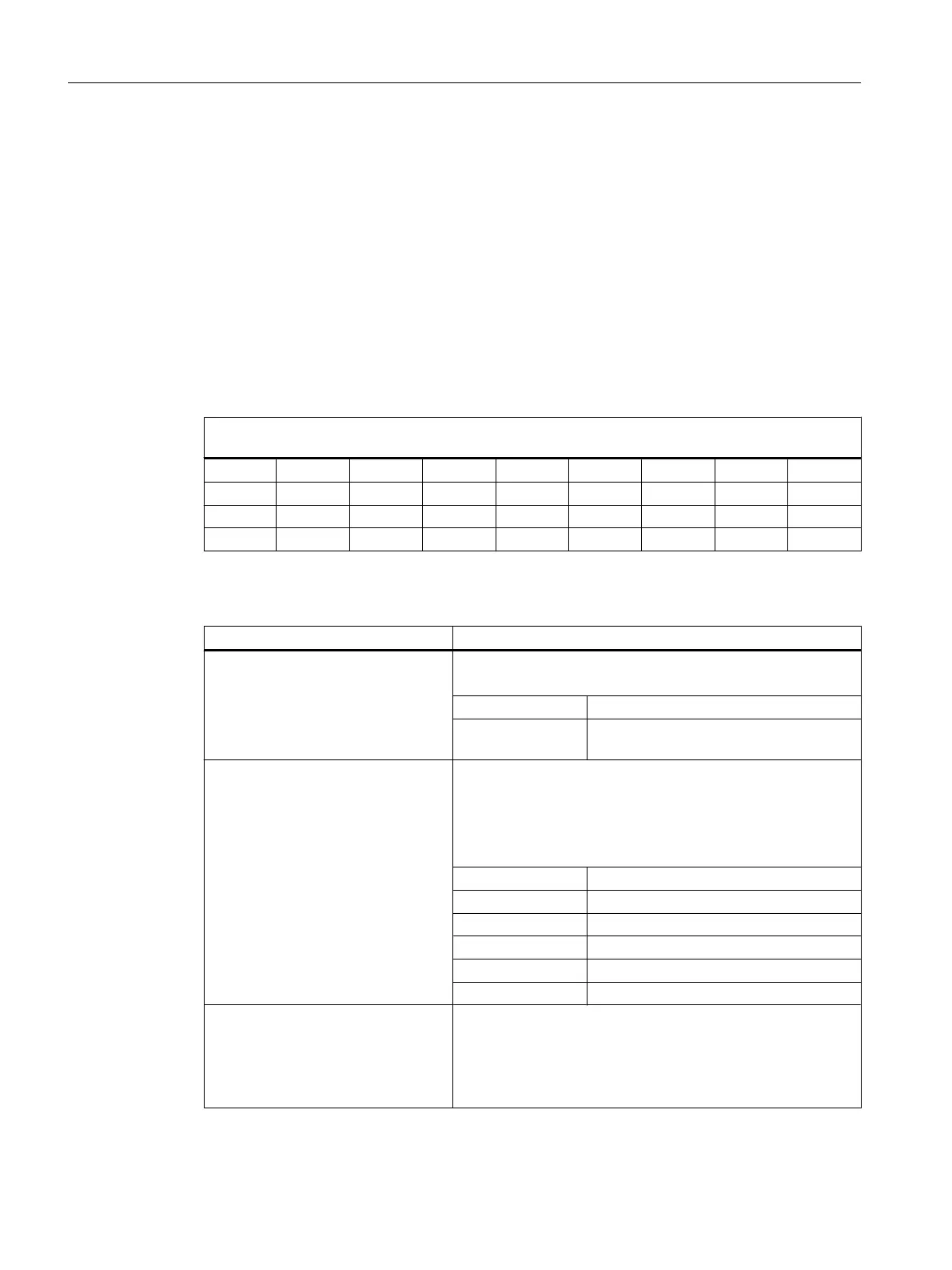
Signals to the MCP1 (or MCP2)
Interface PLC → HT 8
Byte Bit 7 Bit 6 Bit 5 Bit 4 Bit 3 Bit 2 Bit 1 Bit 0
AB n + 1 U4 U3 U2 U1
AB n + 4 U9 U10 U11 U12 U13 U14 U15 U16
AB n + 5 U8 U7 U6 U5
Adapt the display in the "slckcpf.ini" file
Section Description
UserKeyLEDIcon
Name of the icon file.
Standard entry: led_green.png
OFF
Deactivates the icon display.
PRESSED
Displays the active functions by pressing
down the softkey.
UserKeyLEDIconAlignment
Specifies the position of the icon.
Standard position: AlignLeft | AlignTop
Horizontal and vertical alignments can be combined. The two
names are separated by the "|" character.
The following alignments are possible:
AlignLeft Left
AlignRight Right
AlignHCenter Horizontal, center
AlignTop Top
AlignBottom Bottom
AlignVCenter Vertical, center
UserKeyLEDMap
Specifies the start address of the output image.
Entries can be made in the following form: "DBx.DBBy", "ABx",
"MBx".
Default setting: The start address is determined using
DB7 MCP1Out (or MCP2Out).
HT 8
24.3 Configuring the function display at user-specific keys (U keys)
SINUMERIK Operate (IM9)
688 Commissioning Manual, 12/2017, 6FC5397-1DP40-6BA1

 Loading...


