Cable Details and Pinout Information
18
TPI-PRO-DVI - Instruction Manual
Cable Details and Pinout Information
Overview
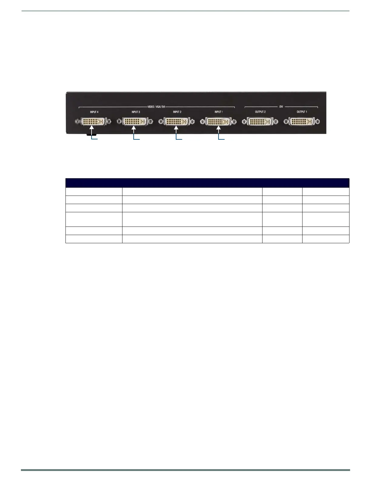
The DVI-I Input connectors on the rear panel (labeled "VIDEO/VGA/DVI Inputs") are used to connect source input devices to the
TPI-PRO-DVI (FIG. 4). The TPI-PRO-DVI routes video from connected source input devices to the connected output devices. Each
connector supports DVI as well as VGA, S-video, Composite and Component inputs.
In order to connect non-DVI input source devices (S-Video, Composite, VGA, and Component) to the DVI Input connectors, the
following (optional) adapter cables are required:
FIG. 4
VIDEO/VGA/DVI Inputs
DVI Input Adapter Cables
Name Description Length FG#
• CC-DVI-DVI DVI-to-DVI 9’ (2.743m) FG10-2170-06
• CC-DVI-5BNCM DVI-to-5 BNC Male 6’ (1.828m) FG10-2170-08
• CC-DVI-RCA3M DVI-to-3 RCA Male
Note: Used for Component and Composite inputs
6’ (1.828m) FG10-2170-09
• CC-DVI-SVID DVI-to-S-Video 9’ (2.743m) FG10-2170-10
• CC-DVIM-VGAF DVI-to-VGA (up to 1920x1200) 6’ (1.828m) FG10-2170-13
DVI-I Input 4
Note: The TPI-PRO-DVI-4 (shown here) has four DVI-I Inputs, the TPI-PRO-DVI-2 has two DVI-I Inputs
DVI-I Input 3 DVI-I Input 2 DVI-I Input 1
 Loading...