Wiring and Device Connections
27
TPI-PRO-DVI - Instruction Manual
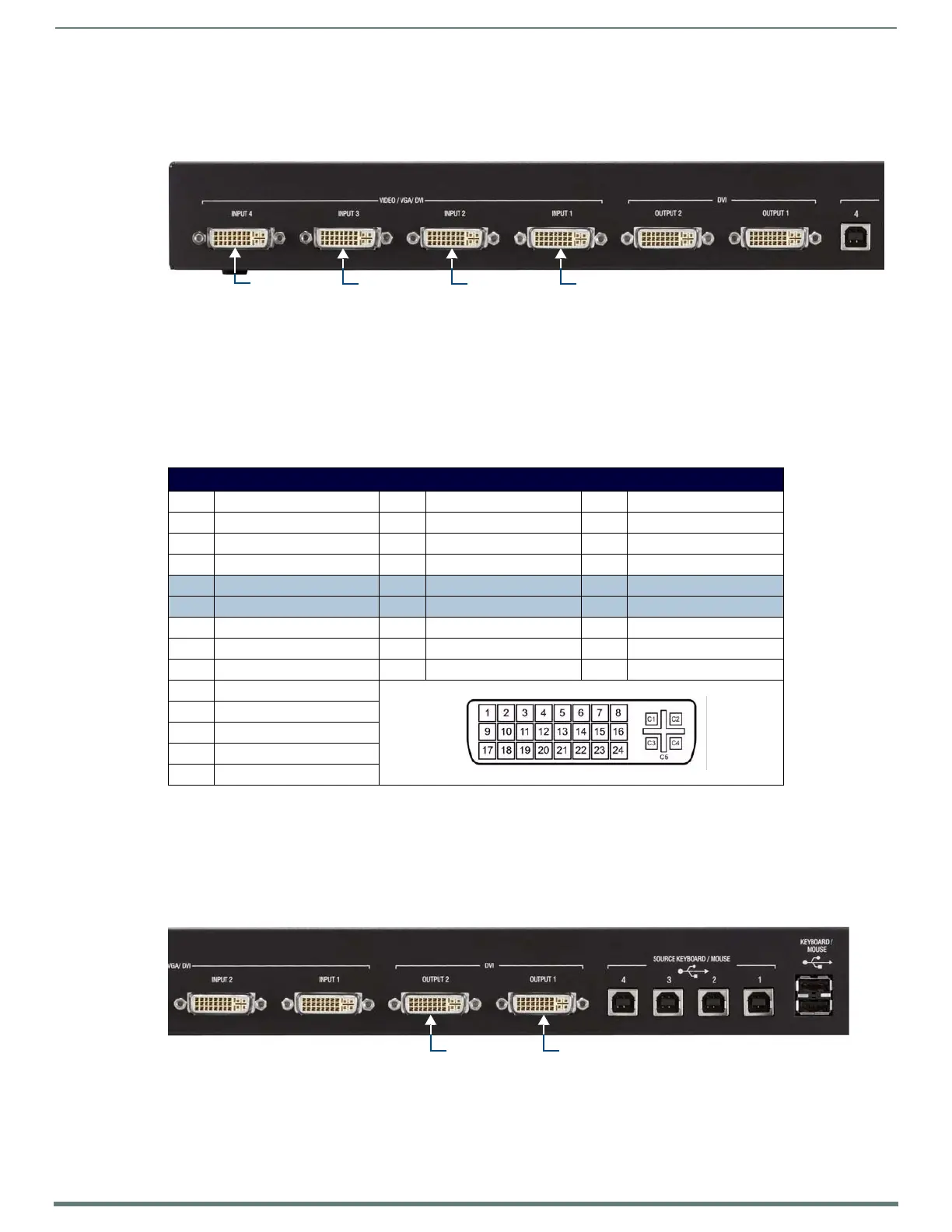
VIDEO/VGA/DVI Inputs
The DVI-I Input connectors on the rear panel (labeled "VIDEO/VGA/DVI Inputs") are used to connect source input devices to the
TPI (FIG. 10). The TPI routes video from connected source input devices to the connected output devices. Each connector supports
DVI -I, DVI-A and DVI-D, as well as VGA, S-video, Composite and Component inputs.
These numbered inputs (1-2 on the TPI-PRO-DVI-2, 1-4 on the TPI-PRO-DVI-4) correspond to the numbered USB (Type B) Device
ports (labeled "SOURCE KEYBOARD/MOUSE").
DVI-I Input Ports - Pinouts and Signals
NOTE: The DVI Input connectors on the TPI are DVI-I (integrated digital/analog) connectors. These connectors support both DVI-A
(analog) and DVI-D (digital) inputs. While less commonly used, they support DVI-I inputs as well.
The following table describes the pinout configuration of the DVI-I Input connectors on the TPI:
When using a DVI source, set the Input Type to DVI (see the Setup - Video Settings Page section on page 59 for details) before
attaching the DVI cable to the TPI. If a DVI source is attached before setting the input to DVI, you may need to reboot the source for
it to recognize the DVI input description information required by the DVI standard.
DVI-I OUTPUT Connectors
The two DVI-I Output connectors on the rear panel are used for connecting the TPI to up to two display devices (FIG. 11). Each
connector supports DVI and analog VGA output. The display devices connected to these outputs will display the video from the
source input devices routing through the TPI, as determined by the panel design.
NOTE: The pinouts and signals on the DVI Output connectors are identical to the DVI Input connectors.
FIG. 10
VIDEO/VGA/DVI Inputs
DVI-I Input Ports - Pinouts and Signals
Pin Signal Pin Signal Pin Signal
1 TMDS Data2- 9 TMDS Data1- 17 TMDS Data0-
2 TMDS Data2+ 10 TMDS Data1+ 18 TMDSData0+
3 TMDS Data2/4 Shield 11 TMDS Data1/3 Shield 19 TMDS Data0/5 Shield
4 n/c 12 n/c 20 n/c
5 n/c 13 n/c 21 n/c
6 DDC Clock [SCL] 14 +5 V Power 22 TMDS Clock Shield
7 DDC Data [SDA] 15 Ground (for +5 V) 23 TMDS Clock +
8 Analog vertical sync 16 Hot Plug Detect 24 TMDS Clock -
C1 Analog Red
C2 Analog Green
C3 Analog Blue
C4 Analog Horizontal Sync
C5 Analog Ground
FIG. 11 DVI-I Outputs
DVI-I Input 4
Note: The TPI-PRO-DVI-4 (shown here) has four DVI-I Inputs, the TPI-PRO-DVI-2 has two DVI-I Inputs
DVI-I Input 3 DVI-I Input 2 DVI-I Input 1
DVI-I Output 1DVI-I Output 2
 Loading...