Wiring and Device Connections
28
TPI-PRO-DVI - Instruction Manual
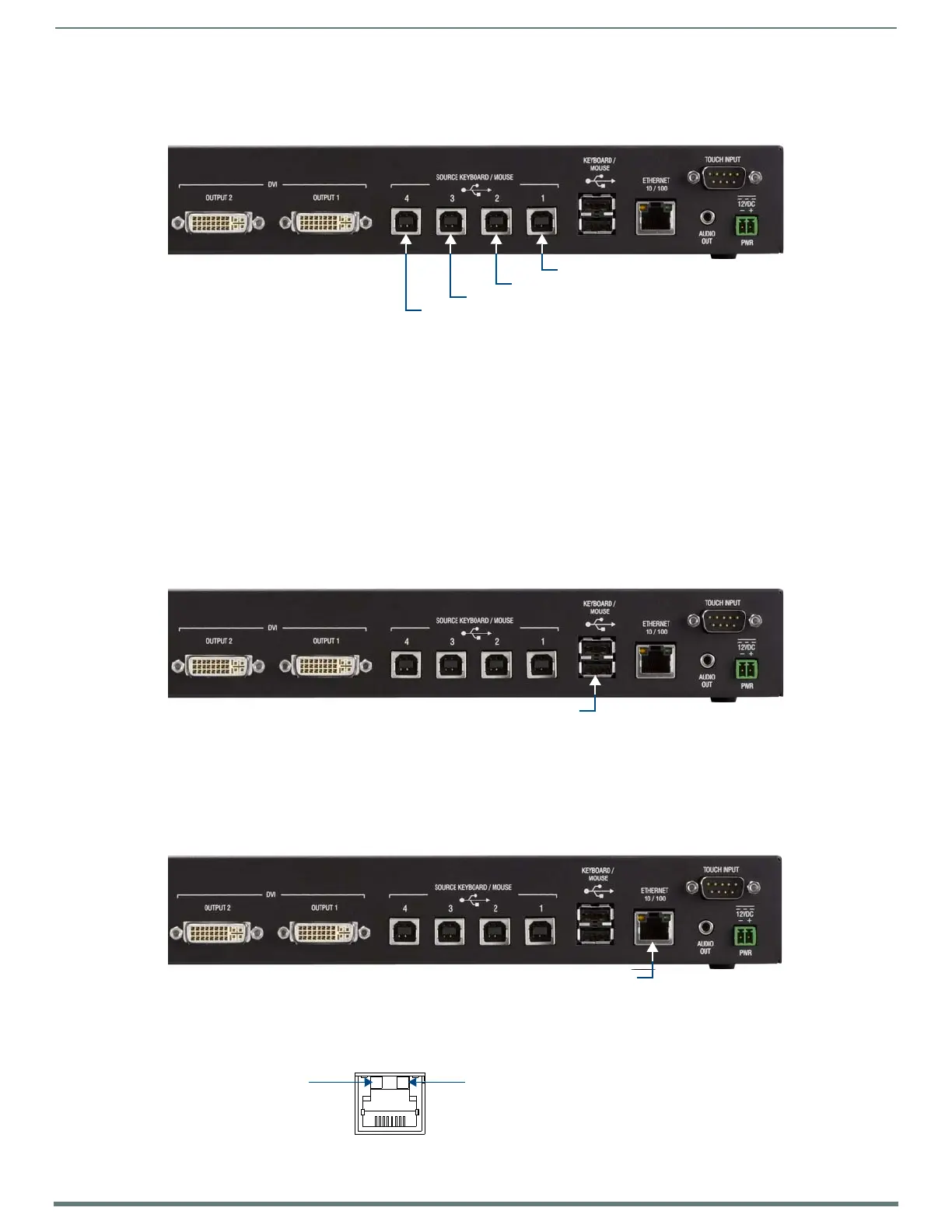
SOURCE KEYBOARD/MOUSE (USB-Type B) Device Ports 1-4
The USB (Type B) Device ports on the rear panel (labeled "SOURCE KEYBOARD/MOUSE") are used to connect up to four source PCs
to the TPI to provide pass-through control for the connected PCs (FIG. 12).
NOTE: The TPI requires that the host PC uses USB v2.0.
The TPI-PRO-DVI-2 has two USB-Type B Device Ports (corresponding with DVI Inputs 1-2)
The TPI-PRO-DVI-4 has four USB-Type B Device Ports (corresponding with DVI Inputs 1-4)
These numbered USB Device ports correspond to the numbered DVI Inputs:
1. The PC connected to USB Device port #1 has pass-through control of the input device connected to DVI Input #1.
2. The PC connected to USB Device port #2 has pass-through control of the input device connected to DVI Input #2.
3. The PC connected to USB Device port #3 has pass-through control of the input device connected to DVI Input #3 (TPI-PRO-
DVI-4 only).
4. The PC connected to USB Device port #4 has pass-through control of the input device connected to DVI Input #4 (TPI-PRO-
DVI-4 only).
USB (Type A) Input ports
The two USB (Type A) Input ports on the rear panel are used to connect USB touch/input devices to the TPI (FIG. 13).
NOTE: Touch/input devices can consist of any combination of a keyboard, mouse, or USB-capable touch screen.
Note that there are two additional USB (Type A) Input ports on the front panel (see FIG. 8 on page 25). All of the USB Input ports
have the same functionality; they are provided on both sides of the TPI for ease-of-access.
ETHERNET 10/100 (RJ-45) Port
The ETHERNET 10/100 (RJ-45) port provides 10/100 Mbps communication with the NetLinx Master via ICSP protocol (FIG. 14).
The Ethernet port automatically negotiates the connection speed (10 Mbps or 100 Mbps), and whether to use half duplex
or full duplex mode.
FIG. 15 describes the blink activity for the ETHERNET 10/100 Base-T RJ-45 connector LEDs.
FIG. 12
SOURCE KEYBOARD/MOUSE (USB-Type B) Device Ports
FIG. 13 Rear Panel USB (Type A) Input Ports
FIG. 14 ETHERNET 10/100 (RJ-45) Port
FIG. 15 ETHERNET connector / LEDs
USB (Type B) Device Port 1
USB (Type B) Device Port 2
USB (Type B) Device Port 3
USB (Type B) Device Port 4
2 USB (Type-A) Input ports
ETHERNET 10/100 (RJ-45) port
A L
A - Activity LED (yellow)
lights when receiving or
transmitting Ethernet
data packets
L - Link LED (green) lights when
the Ethernet cables are connected
and terminated correctly.
 Loading...